U= lmbo^qflk=
UKN= léÉê~íáçå=éêÉÅ~ìíáçåë=
• Make sure that the power switch is set to “off” before connecting any input or output, or
operating the switches on the rear panel. See page 10
regarding installation.
• Make sure that the AC mains voltage is correct, and the same as the one printed on the rear
panel of the amplifier. See page 10
regarding operating voltage and power consumption.
• Make sure that the switches on the rear panel for operation modes, gain switch, clip limiters,
and the MLS switch are in the correct position. See page 7
regarding operation modes, page 15
regarding clip limiters, and page 8
regarding the MLS switch.
• It is always a good idea to turn down the gain controls during power-up to prevent from speaker
damage in case of a high signal being present at the input.
UKO= mçïÉêáåÖ=ìé=Ó=pçÑí=ëí~êí=
When you power up the amplifier it takes a couple of seconds to check its circuits. This is known as the
"soft-start" or "slow-start" sequence. The fans first blow at high speed before going into "idle", and the
two bottom green LED’s illuminate to show that the amplifier is operational.
UKP= fåéìí=~ííÉåì~íçêë=
The two input level attenuators on the front panel adjust the signal level for their respective amplifier
channel in all modes. They are calibrated in dB to assist the setup of active loudspeaker systems, or to cut
down unwanted noise from the input signal.
In bridge mode both controls must be in the same position, so that the speaker load will be shared equally
between the channels.
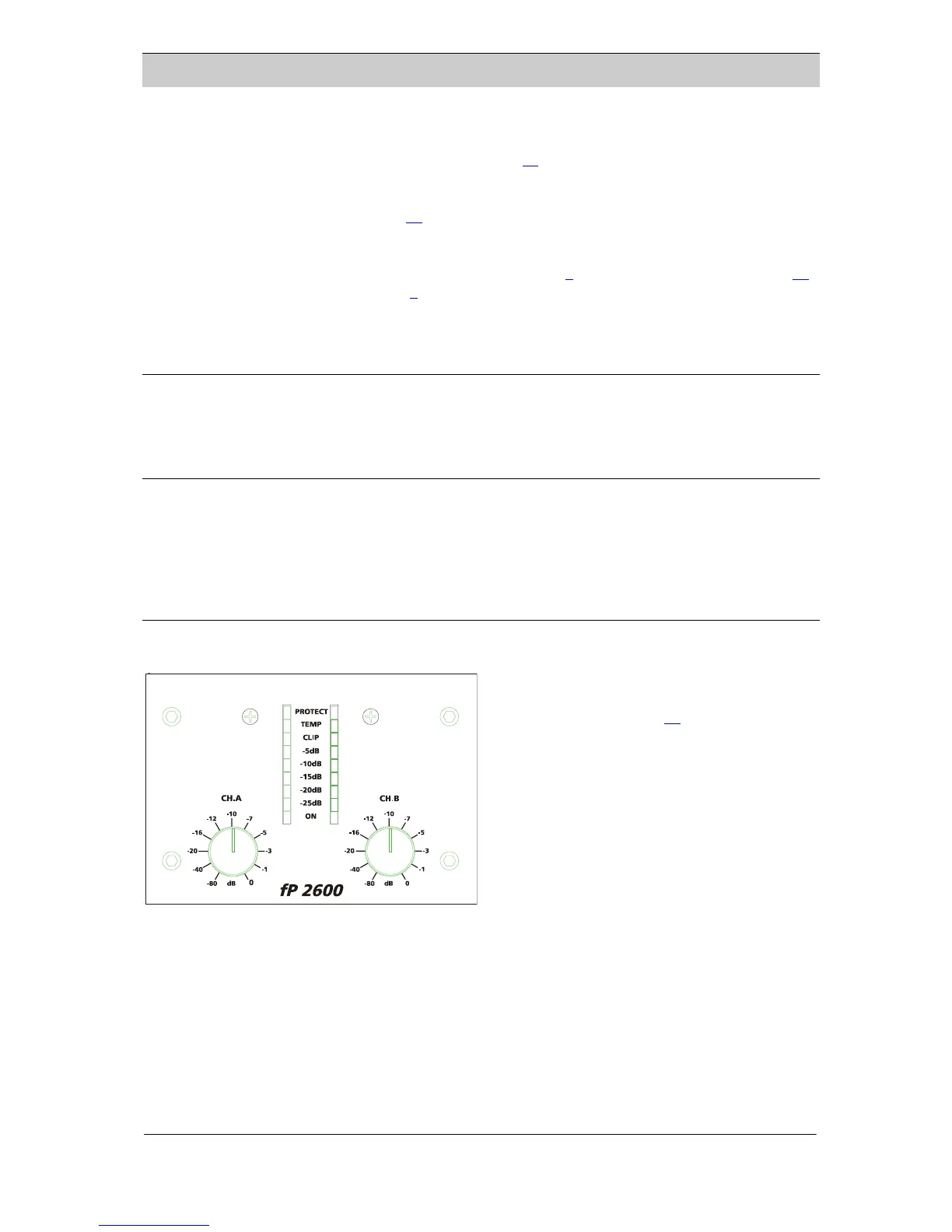
UKQ= fåÇáÅ~íçêë=
The yellow LED’s indicate if any protection
circuits are activated. The protections are described
further below on this page (15
).
The Clip indicator tells if the amplifier output is
clipping or limiting. It has two different indication
statuses:
• If the clip limiter is enabled, it has a short time
constant, and it illuminates briefly.
• If the clip limiter is disabled, it has an in
time constant, and it illuminates for a longer
period.
creased
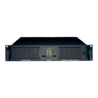
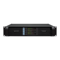
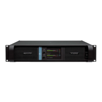
Front panel indicators
The ”-25dB” LED’s illuminate if the output signal is greater than -25dB (with 0dB as reference to full
output power). These LED’s also act as signal presence indicators.
The rest of the green LED’s form a bar for output levels from -20dB to -5dB.
The green bottom ”ON” LED’s indicate that the output circuits are receiving the correct rail voltage.
i~ÄKÖêìééÉå== = = = = ====================== ========================NQ
rëÉê=j~åì~ä===Ñm=OSMM======sÉêëáçå=MKV========OMMPJNMJMT=

 Loading...