Changing the DIP switch settings
If you need to change settings, follow the steps below to make your
changes:
CAUTION:
Turn off the printer while removing the DIP switch cover to prevent an
electric short, which can damage the printer.
1. Make sure the printer is turned off.
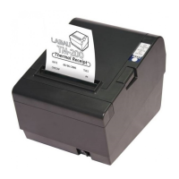
2. Remove the screw from the DIP switch cover. Then take off the
DIP switch cover, as sown in the illustration below.
3. Set the switches using a pointed tool, such as tweezers or a small
screwdriver.
4. Replace the DIP switch cover. Then secure it with the screw.
The new settings take effect when you turn on the printer.
A-6
Dip Switch and Paper Near End Settings
APPENDIX B
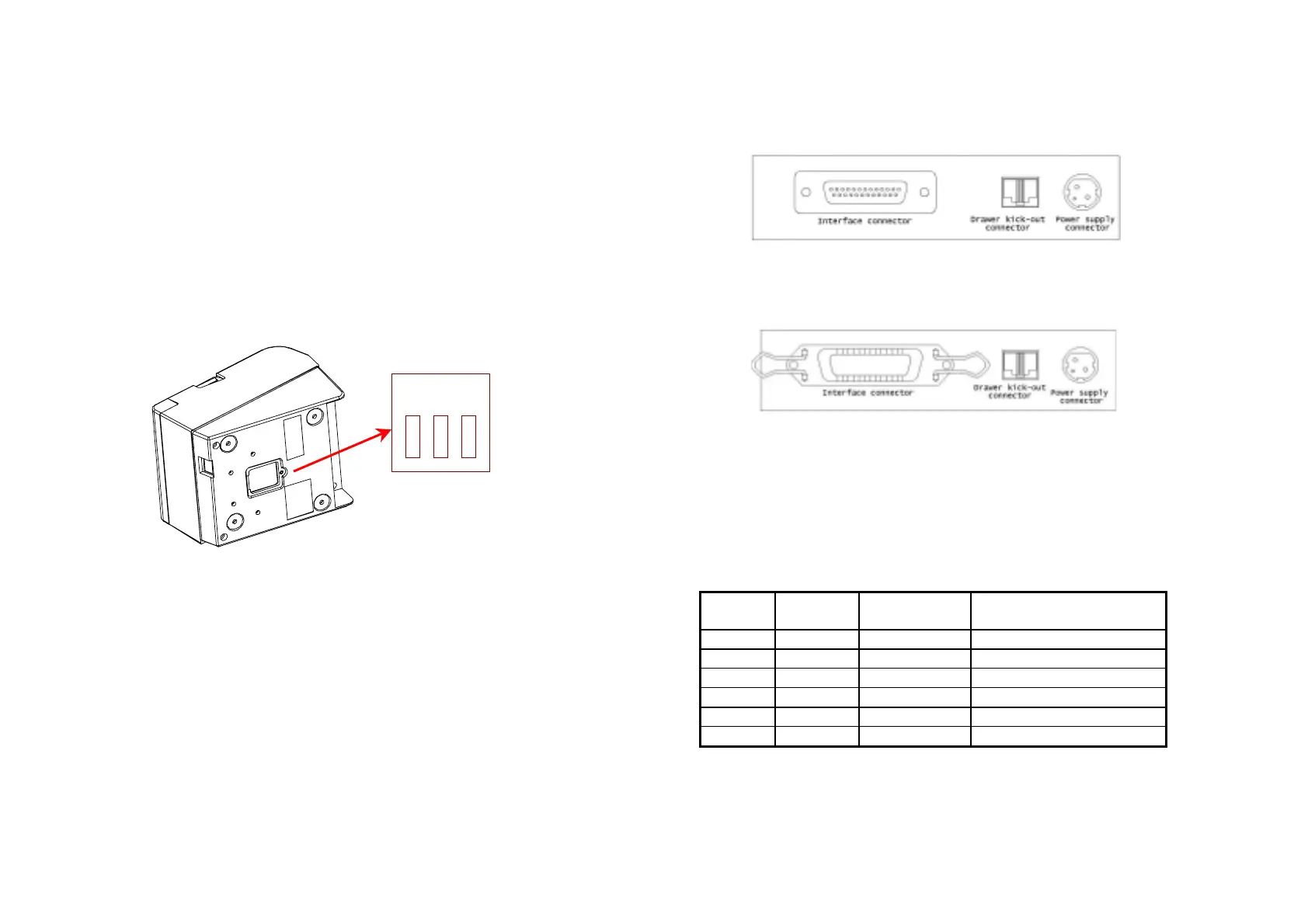
Connectors
TM200 Connector
(Serial interface)
TM200 Connector
(Parallel Interface)
Interface Connector
Serial Interface (RS-232)
Pin No.
Signal
name
Direction Function
1
FG - Frame Ground
2
TxD Output Transmit Data
3
RxD Input Receive Data
6
DSR Input Data Set Ready
7
SG - Signal Ground
20
DTR Output Data Terminal Ready
A–7
Sw3
Sw2
Sw1