INSTRUCTIONS FOR THE INSTALLER 11
2.
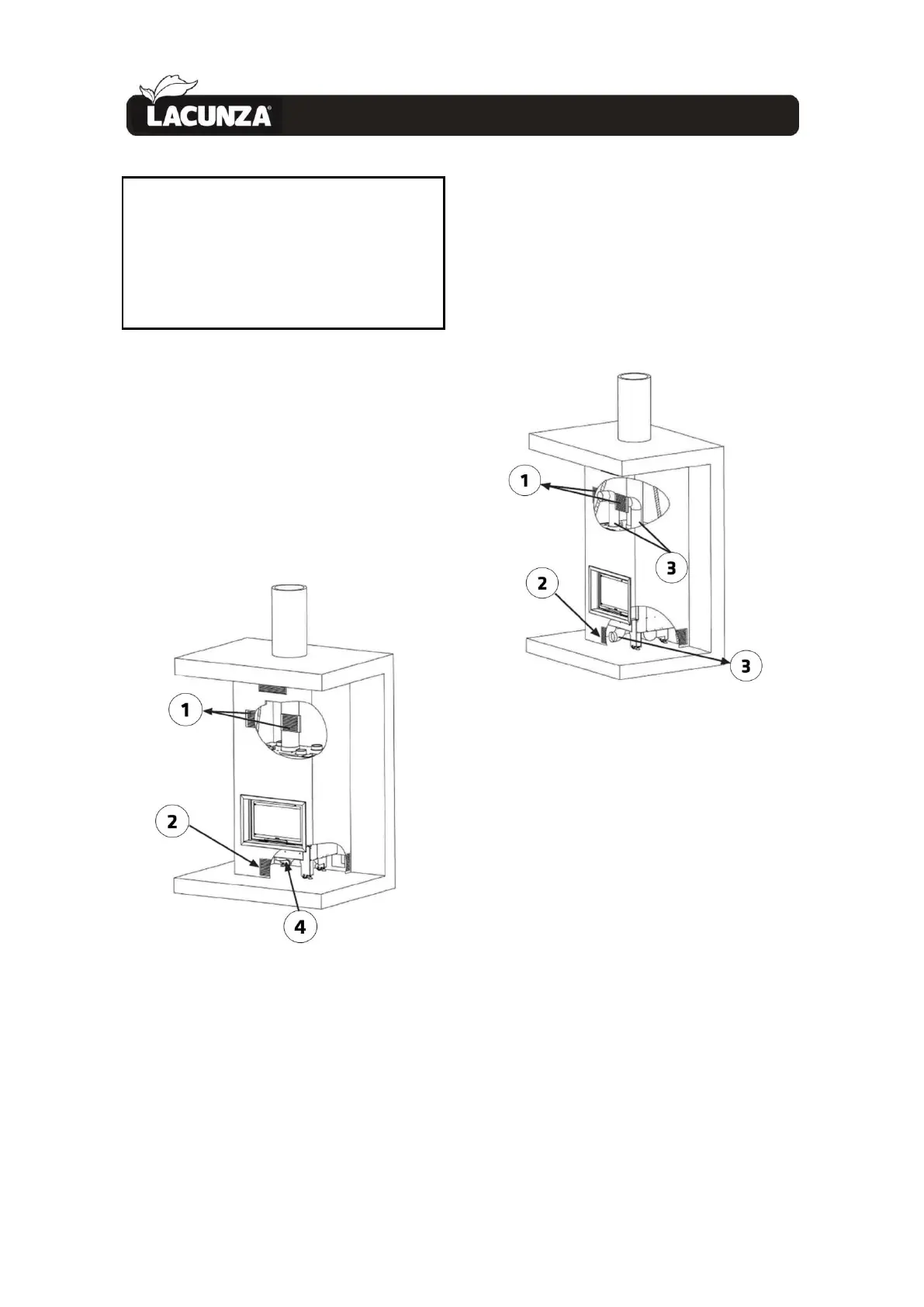
Key to combustion-air intake and hot-air
output installation option diagrams:
1 Hot-air output grille
2 Combustion-air intake grille
3 piping
4 Combustion-air intake nozzle
5 Combustion-air intake from outdoors
OPTION A: Combustion-air intake from
inside the room and hot-air output by
natural convection (without fan).
With this option, it is not necessary to
lead the hot air along piping to the hot-air
output grilles, as shown in the image, or
from the combustion-air intake grille to the
combustion-air nozzle that feeds
combustion air to the firebox.
Figure No.9 - Image showing Option A
OPTION B: Combustion-air intake from
inside the room and hot-air output by
forced convection (with fan).
With this option, the hot air can be led
along piping from the hot-air output
nozzles on the appliance to the hot-air
output grilles on the casing or to other
rooms. The air flow required at any given
time can also be regulated via the
potentiometer on the fan. Up to 4 outputs
can be fitted (the nozzles not to be used
should be capped). In such cases, the
combustion-air intake must be led via
piping from the grille on the outside of the
casing to the combustion-air intake nozzle
so that it does not interfere with the air
drawn in by the fan.
Figure No.10 - Image showing Option B
OPTION C: Combustion-air intake from
outside the room and hot-air output by
natural convection (without fan).
With this option, the combustion-air
intake is led from outside the room in
which the appliance is fitted (other room
or outdoors) to the combustion-air intake
nozzle via piping with a diameter of
120mm and it is not necessary to lead the
hot air coming out of the nozzle on top of
the appliance to the hot-air output grilles
on the casing with piping.
 Loading...