INSTRUCTIONS FOR THE INSTALLER 12
2.
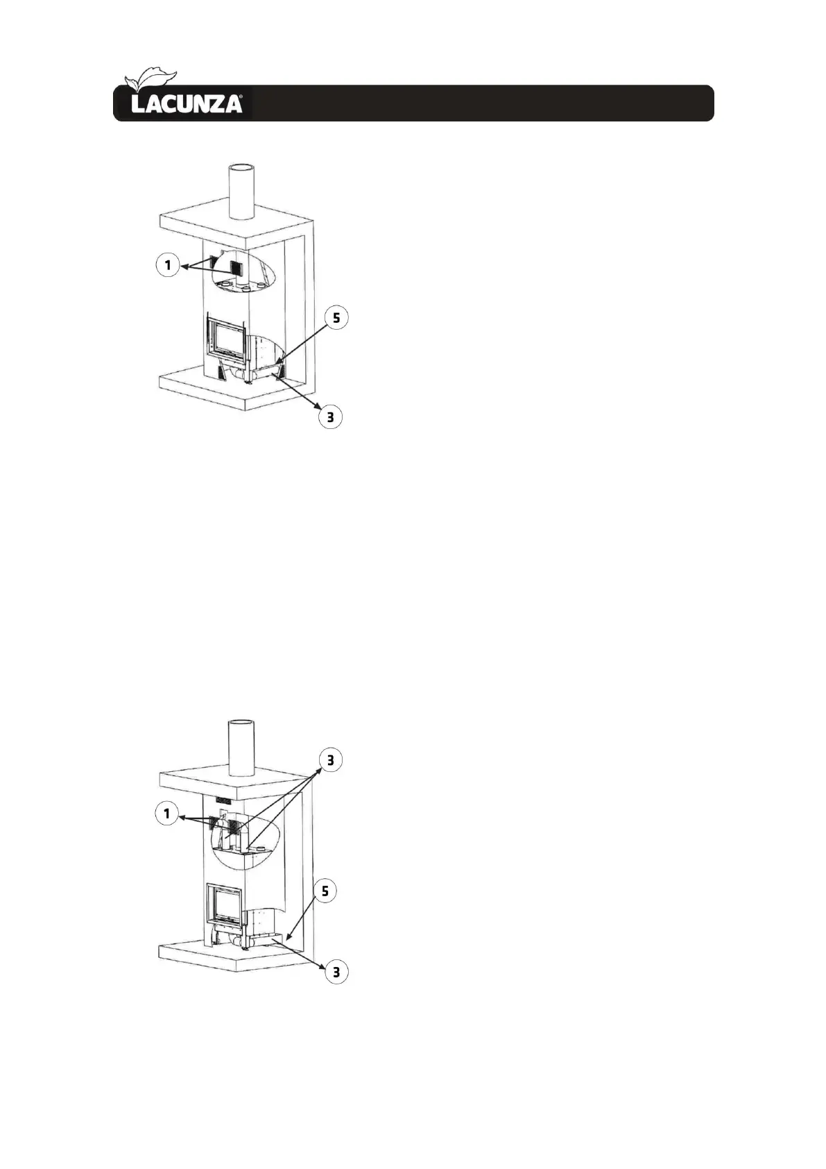
Figure No.11 - Image showing Option C
OPTION D: Combustion-air intake from
outside the room and hot-air output by
forced convection (with fan).
The installation system for this option is
the same as that of the previous option,
but also involves leading the hot-air output
from the nozzles on top to the hot-air
output grilles or to other adjoining rooms
via piping with a diameter of 120mm. The
nozzles on top of the appliance not to be
used should be capped.
Figure No.12 - Image showing Option D
WARNING!: When the appliance has a
fan (C/V option), it is important that the
shell is well ventilated through both the
upper and lower grilles on the casing.
Respect the minimum sections
recommended for the grilles (larger grilles
are no problem); otherwise, overheating
problems may arise inside the shell and
excess air temperatures may cause the fan
to stop by triggering its overload safety
system (in this case, due to excess
temperature).
The combustion air intake (through the
120mm-diameter nozzle on the front-
bottom of the appliance, which can be
piped in from outdoors) MUST be fully
independent from the fan air intake
(through the grilles at the bottom of the
sides of the casing, which draw air in from
the room the appliance is fitted in)
because they are separate air circuits.
WARNING: In all cases involving piping
to lead hot air, the piping must be
insulated and tend or slant upwards; never
downwards. Bends, bottlenecks and
horizontal sections more than 1m long
should be avoided as much as possible.
Bear in mind that the air circulating along
the piping loses speed as it advances due
to friction with the walls and the reduction
in temperature. The ends of the piping
used to lead air must be well sealed with
fire sealant or fire cement. We recommend
that the pipes used for forced convection
do not exceed 4 metres in length.
2.3.9. Exterior Frame. Removal and
assembly
If you need to remove the exterior
frame from the appliance (casing,
transportation, etc.), proceed as follows:
• Unscrew the 2 sliding knobs that
control inlets 1 and 2 and remove them.
 Loading...