INSTRUCTIONS FOR THE INSTALLER 13
2.
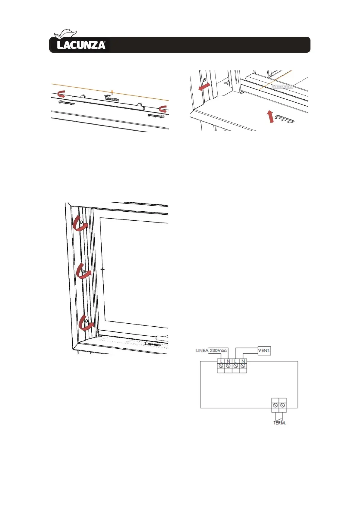
Figure No.13 - Unscrew the 2 sliding knobs for
inlets 1 and 2
• Unscrew the 6 M6 screws that
secure the sides of the frame.
Figure No.14 - Unscrew the 6 screws that
secure the exterior frame
• Remove the frame from its
housing, being careful not to damage
the enamel. First lift the frame to free
the screws made visible by removing
the sliding knobs and then pull it
forwards.
Figure No.15 - Removing the frame
• Perform the removal process in
reverse order to refit the frame
2.3.10. Fan-potentiometer connection
(only for models C/V)
ITACA c/v models (the models with
fans) are prepared for connection on the
potentiometer supplied. The appliance has
2 hoses protruding from it:
• PROBE hose (TERM), 2 wires.
• Fan hose (VENT), 3 wires.
The two hoses are connected to the
potentiometer according to the connection
diagram in the potentiometer instruction
manual.
The 3-wire power hose for the fan
(LINEA) is not supplied and must be
connected by a person qualified to install
it.
Figure No.16 - Connections to make on the
Itaca fan potentiometer