4. Product Overview
This chapter provides an overview of key features and functionality. For further information please see
chapters 5 to 9 of this Operation Manual.
4.1 Front Panel Overview
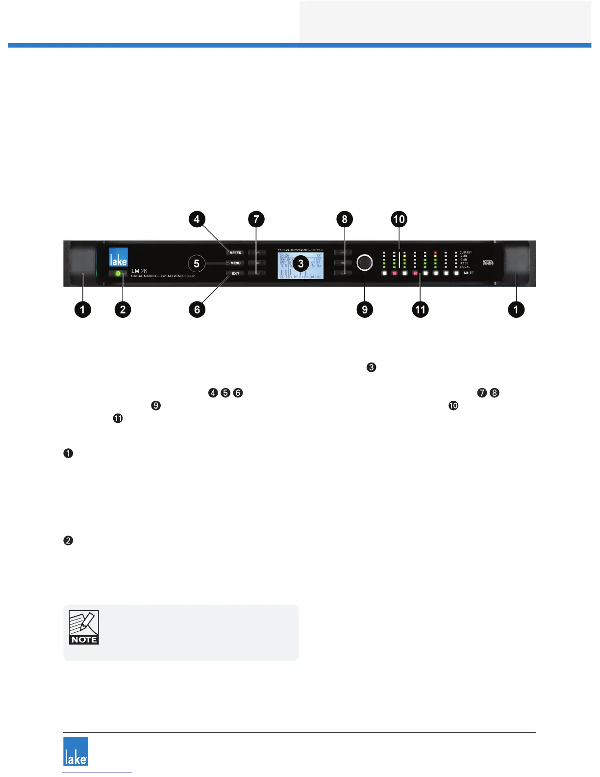
Figure 4-1: LM Series Front Panel Overview
The front panel controls are clustered around a daylight readable LCD , allowing adjustment and monitor-
ing of the majority parameters and meters. The two clusters of controls on either side of the LCD include
three dedicated function buttons , six dynamic function buttons with embedded LEDs and a
rotary data encoder . To the right of these controls is a dynamic illuminated I/O divider along with input
and output mute buttons and level meters.
Handles
Two sturdy cast aluminium handles are integrated into the front panel. The handles should be used when
carrying the device, and when tting into or removing from a rack. Ensure that any door or removable rack
front cover has sufcient depth to clear the handles.
Standby
LM Series devices are powered on and placed into standby mode using the left-most button, or via the
Lake Controller. Standby mode is not equivalent to turning the device off at the mains power.
All audio in and out of the processor is muted when
in Standby mode. Network communication remains
active to allow the device to be turned on via the
Lake Controller.

 Loading...