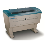
Screw 1
Pivot Screw
Screw 2
Pivot Screw - do not adjust
Adjust screws 1 and 2 only on any prism mount. One will be front to rear, while the other will be
left and right. Mirror 1’s prism mount is displayed below. See bottom image to determine how to
adjust screws 1 and 2.
Adjust the prism mount of Mirror 1 to move the burn mark into the center of the lens carriage.
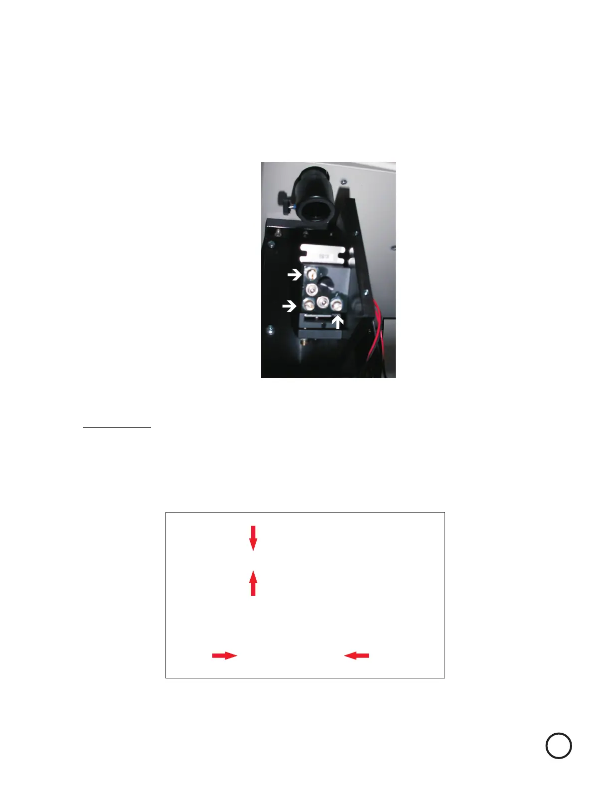
Screw 1
Clockwise
Counter
Clockwise
Rear of machine
Front of machine
Screw 2
Clockwise
Counter Clockwise
Lock Screws must be tightened when adjustments completed. Adjustments should
be made with lock screws snug, they may need to be loosened slightly if adjustment
is made on screws 1 or 2 in a clockwise direction. (Please note tightening up Lock
Screws may affect beam alignment adjust alignment as necessary)
Remember to always wear safety glasses while doing any open beam tests.
Remove the vent plate on the left side, bottom, of the machine and remove the two thumb screws
and the black mirror 1 cover.
9