- 10 -
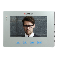
Color monitor MVC-8151
5. Installation and activation of the monitor
Execution of electrical installation
Detailed recommendations regarding the electrical installation of the video door entry sys-
tem can be found in the operating instructions of the CD-2502 or CD-3100 digital door pho-
nes.
The installation should be done using video splitters. You need one splitter for four mo-
nitors.Thesplittercanactasacentralpowersupply,providedthatitispoweredfromthe
15VDC/4A power supply. With this connection the distance between the splitter and the mo-
nitorshouldnotexceed30m,accordingtothetableinFigure4.Themonitorcanalsobepo-
weredfromalocalpowersupply13,5V/1,2A.Thisisrecommendedifthedistancebetween
the external panel and the monitor exceeds 30m. The video signal should still be fed from
the CVR-2 splitter. For video installations it is recommended to use UTP cat.5.5.
Monitor installation
Monitorshouldbemountedinsidethebuildinginaplaceeasilyaccessibletotheresidents,
ataheightofatleast1,5minsuchawaythatitdoesnotposeathreattothemandisnot
exposed to accidental hit.
Do not install the monitor in front of a window or strong light source as this may make it dif-
culttoobservetheimageonthemonitorscreen.Itisnotrecommendedtoinstallmonitors
innarrowcorridorsorpassageways,asthismaycausesounddistortion.
Themonitorshouldbemountedatleast1,5mfromsourcesofstrongelectromagneticinter-
ference–transformerpowersupplies,magnets,metalsewerandgaspipes,asthismaycau-
seimagedistortion.Itisrecommendedtoplaceaush-mountedelectricalboxwithaxing
socket or an electric switch in the place provided for the monitor installation. Connect the
monitor connection cables in a box. Attach the monitor mounting bracket to the box so that
the holders with the holes will be directed up. Attach the mounting plugs to the cables (Fi-
gure5and6).Inserttheplugsintotheappropriatesockets,remembertoputthepowerplug
at the end.
Programthemonitornumber(seesection6„Programmingthenumber”).
Finallyattachthemonitortothemountingbracketandlightlypullitdown,overcominga
slight resistance.
Terminals Distance
<15m <30m
L+,L-,CAM1+,CAM1-
0,5mm
+VS,GS
0,5mm 2x0,5mm
Figure 4. Permissible monitor-distributor distances and required cable diameters


 To Next Page