- 13 -
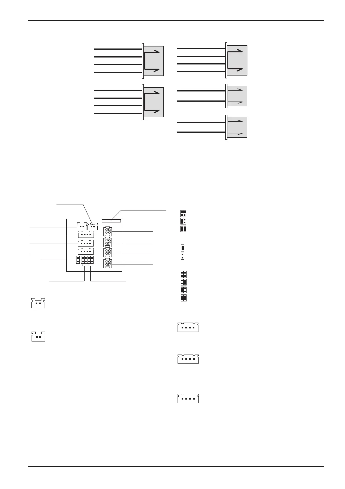
Color monitor MVC-8151
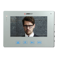
CN-CAM2
CN-CD
CN-BP
CN-PWR
CN-BELL
red
black
white
blue
red
black
white
blue
red
black
white
blue
red
black
red
black
VC GND
PORT
NO
NO
+VS
GS
BELL
GND
GND
C2
AUD
CAM1+
CAM1-
L-
L+
P1 (MIC1)
CN_BELL
CN_PWR
PROG connector*
CN_BP
CN_CAM2
JP2
JP1 JP3
CN_CD
P2 (BAL1)
P4 (BAL2)
P3 (MIC2)
CN_PWR
1 - +VS - monitor power supply
2 - GS - monitor power supply (ground)
JP1 – C+, C- line conguration (CAM1+, CAM1-)
JP2 – VC line conguration of connector CN_CAM
BNC – coaxial cable
TERM OFF
C2 TERM 75R
C1 TERM 75R
UTP – UTP twisted pair
UTP+TERM – UTP twisted pair with 100R terminator
1,5V in standby mode
5V in standby mode
JP3 – C1 and C2 line conguration for coaxial cable
1 2
CN_BELL
CN_BP
1 - BELL - doorbell
2 - GND - doorbell (ground)
1 – GND – ground
2 – PORT – porter line
3 – NO – gate drive control
4 – NO – gate drive control
1 2
1 4
CN_CAM
1 – VC – power supply for additional camera
/ oor panel
2 – GND – ground
3 – C2 – video signal from the additional camera
4 – AUD – audio line of the oor panel
1 4
CN_CD
1- CAM1+ video signal from the door entry system
2 – CAM1- video signal from the door entry system
3 – L- line of handsets
1 4
* The programming connector is used in the production
process and for service purposes
NOTE!
Removing the plastic cover from the programming
connector will void the manufacturer's warranty!
C1 TERM 75R, C2 TERM 75R
Figure 5. Description of the monitor connection plugs
Figure 6. Description of the monitor connection sockets. Control elements and congura-
tion jumpers
 Loading...