Unit description
6
3.7 Serial Interfaces RS 232, RS 485
3.7.1 Specification and interface test
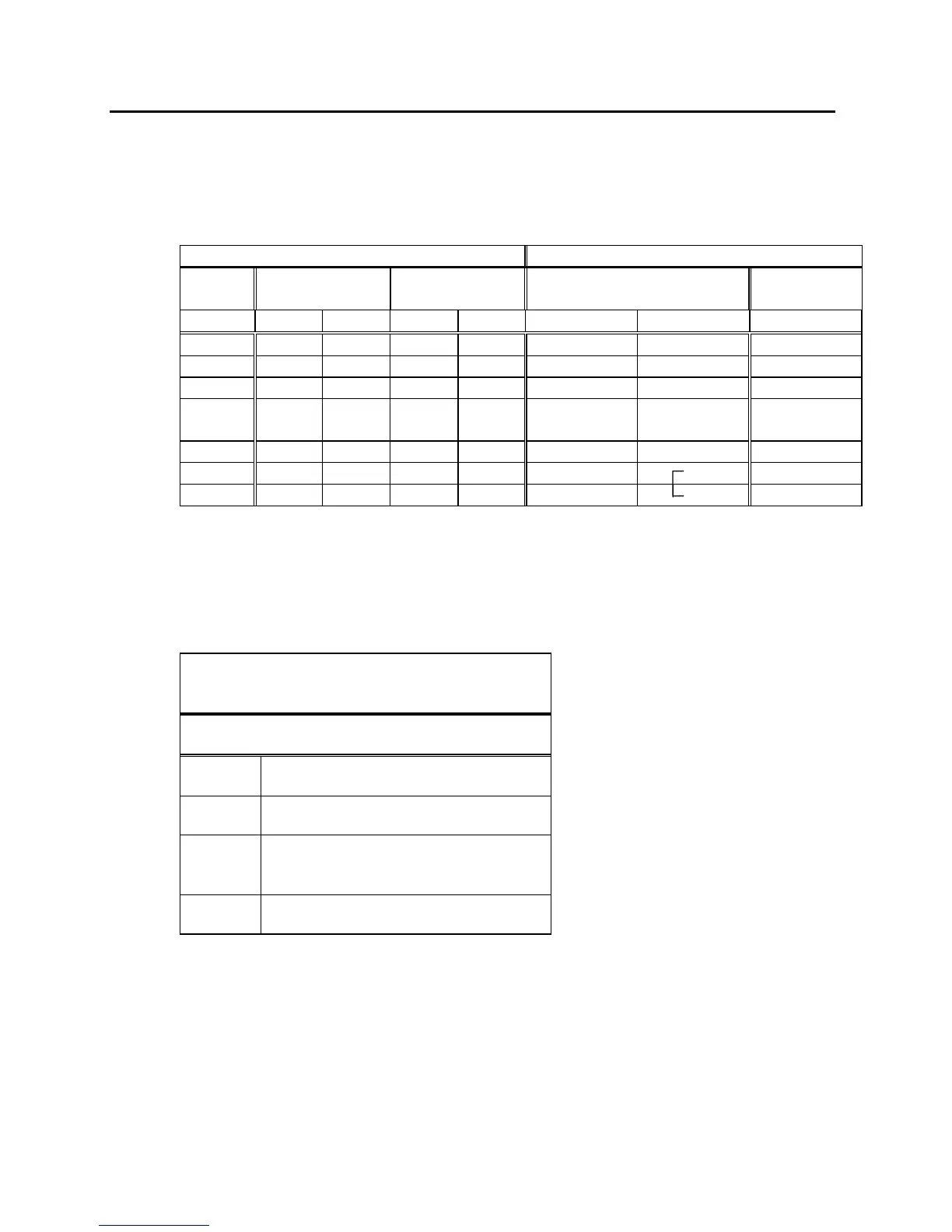
Computer
Thermostat
Data
9-pin sub-D
socket
25-pin sub-D
socket
9-pin sub-D socket
Data
① ② ① ② ① ②
R x D 2 2 3 3 2 2 T x D
T x D 3 3 2 2 3 3 R x D
DTR 4 20 4 DSR
Signal
Ground
5 5 7 7 5 5 Signal Ground
DSR 6 6 6 DTR
RTS 7 4 7 7 CTS
CTS 8 5 8 8 RTS
☞
① with Hardware Handshake: When connecting the thermostat to the computer please
use a 1:1 cable and not a zero-modem-cable!
② without Hardware Handshake: The computer needs an operating mode: ”without
hardware handshake”. In the plug of the thermostat a bridge has to be inserted between
Pin 7 and 8.
Thermostat
RS 485 interface
9-pin sub-D-socket
pin Data
1 Data A
5 SG (Signal Ground)
optional
6 Data B
☞
− Use shielded connecting cables.
− Connect the shielding to the plug case.
− Cover unused connectors with protection caps!
− The lines are electrically isolated from the remaining electronics.
− Unoccupied pins must not be connected!