LAUNCH X-431 PAD V
User's Manual
57
end to the Data I/O port of the diagnostic tool. This connection applies
to outside the vehicle test and inside the vehicle.
*Notes:
1. Wait about 10s and begin to communicate since the Baerybox needs to
inialize aer connecon is complete, otherwise, communicaon may
fail.
2. Red LED on the Baerybox means it has been successfully powered up.
If the green LED is always on, it indicates the clip is well connected; while
the green light blinks, it indicates that the clip has poor contact. Do not
perform any test unl the clip and data cable are properly connected.
7.2.4.2 Inside the vehicle test
Battery test and charging system & actuation system test can be done
in this mode.
1. Battery test
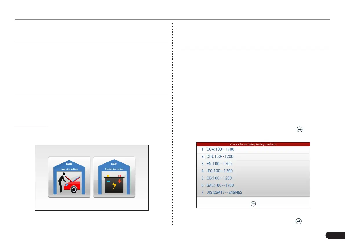
Enter the battery test main menu screen, and select a desired test
environment.
Fig. 7-14
*Note: The sequences of inside the vehicle and outside the vehicle test
are almost the same, but under inside the vehicle condion, all loads in
vehicles must be powered o for geng an exact test value.
1. Firstly, the system detects whether oating electricity exists or not
before testing. If yes, turn on the headlamp to remove it. Otherwise,
the system starts test program directly.
2. Tap [Inside the vehicle], the system starts detecting floating
electricity automatically. If floating electricity is detected, it will
prompt you to turn on the headlamp.
3. Follow the on-screen instructions to turn on headlamp, the system
starts removing oating electricity.
4. Once the oating electricity is removed, a prompt message box “The
oating electricity has been removed, please turn off the headlamp
to continue the testing” will appear on the screen.
5. Follow the on-screen instructions to turn off the headlamp and
tap [OK], the system will continue the testing. Tap , it will enter
testing standard selection screen.
Fig. 7-15
6. Select a testing standard except for JIS and tap to enter the