LAUNCH X-431 PAD V
User's Manual
61
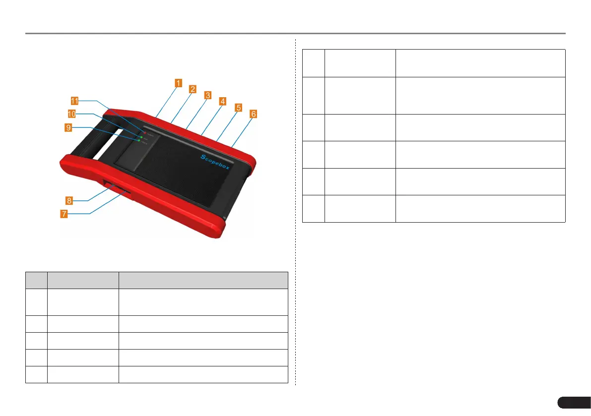
7.3.2 Structure & Accessories
7.3.2.1 Scopebox structure
Fig. 7-20 Scopebox Structure Diagram
Below describes the ports and indicators for the Scopebox.
No. Name Descriptions
1
Fixed signal
generator
Generate a square signal with xed 1K
frequency.
2 CH1 Channel 1
3 CH3 Channel 2
4 CH3 Channel 3
5 CH4 Channel 4
6 External trigger
External trigger signal
(*It only applies if the
Scopebox failed to trigger the signal itself.)
7
B-shaped data I/
O port
Connect to the diagnostic tool via data
cable so that the signal can be displayed on
the tool.
8 Power interface
To provide power to it via the power adapter
or battery clamps cable.
9
Communication
indicator
It blinks in process of data communication.
10 Running LED
It remains steady green after the Scopebox
is running.
11 Power LED
It keeps solid red after the Scopebox is
powered on.
7.3.2.2 Scopebox accessories
The Scopebox includes the auto test leads, secondary pickup cable
for 4-channel oscilloscope, crocodile clips for 4-channel oscilloscope,
etc. See the packing list attached to the product for the detailed
accessories.