Launch TLT235、TLT240 Economical Two-post User’s Manual
12
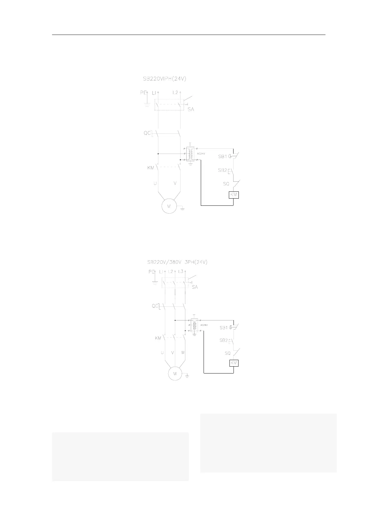
4.2 Electrical System of the Lift
Diagram of electrical system for single phase motor
AC500V20A protective
switch for power needs
to be prepared by
customer
M1-Motor KM-Contactor SB –Button SQ- Limit switch
Fig. 5a
Diagram of electrical system for three phase motor
AC500V20A protective switch
for power needs to be
prepared by customer
M1-Motor KM-Contactor SB –Button SQ- Limit switch
Fig. 5b
The electrical working principle is as follows:
Press the start button (SB), and the contactor (KM) will be
powered; motor (M) is energized to drive the gear pump
supplying oil to push the carriage upward; release the start
button, and the contactor (KM) is open, then the motor (M)
will lose the power, so the carriage will stop rising. As for
the clear-floor lift, if the vehicle is lifted up near the top and
contacts the limit switch on the top beam, the contactor
(KM)) will open, then the motor (M) will lose the power, so
that the carriage stops lifting to avoid hitting the top..
Emergency stop button has the function of emergency
power-off.