TLT235、TLT240 Economical Two-post User’s Manual
17
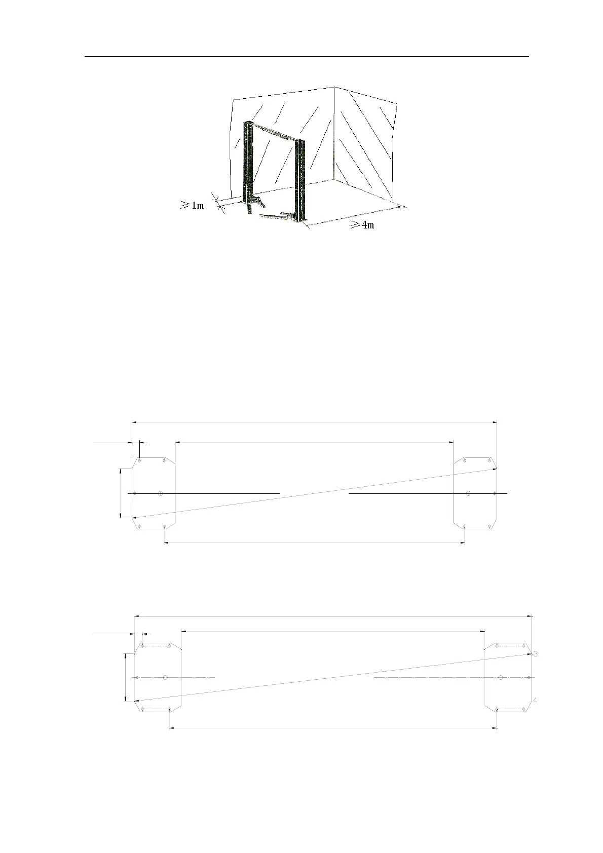
Fig. 8
10.2.2 Base plate layout
TLT235SC(U) symmetric installation is shown in Fig.9a,,
TLT235SC、TLT240SC symmetric installation is shown in
Fig. 9b, TLT235SB、TLT240SB symmetric installation is
shown in Fig.9c:
z With total width (A) as the basis, draw two parallel
lines (#1 and #2) on the concrete slab, with the error
within 3mm.
z Determine the power side column location on any
chalk line, and mark the total width (B) of the base
plate. Mark the points 3 and 4.
z Starting from point 3, draw one diagonal line
(C) ,forming a triangle. In this way, the vertical lines
can determine the location of the two columns.
B
C
A
2#1#
70mm
(2.76in)
3392mm(133.54in)
2582mm(101.65in)
3
4
1
5
.
5
m
m
(
1
3
4
.
4
7
i
n
)
2792mm(109.92in)
400mm(15.75in)
4
3
Fig.9a
400mm(15.7in)
70mm
(2.76in)
TTLT240SC:2610mm(102.76in) TLT235SC:2590mm(101.97in)
TLT240SC:3420mm(134.65in) TLT235SC:3400mm(133.86in)
TTLT240SC:2820mm(111.02in) TLT235SC:2800mm(110.24in)
T
T
L
T
2
4
0
S
C
:
3
4
4
3
m
m
(
1
3
5
.
5
5
i
n
)
T
L
T
2
3
5
S
C
:
3
4
2
3
m
m
(
1
3
4
.
7
6
i
n
)
1#
2#
A
C
B
Fig.9b
Entrance