Do you have a question about the Launch X-431 PRO3 LINK and is the answer not in the manual?
Guidelines for maintaining a safe and organized workspace to prevent accidents.
Precautions to prevent electric shock and hazards associated with electrical components.
Recommendations for operator safety, including protective gear and avoiding hazardous conditions.
Specific warnings and procedures for working with the vehicle's Electronic Control Unit.
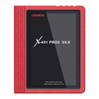
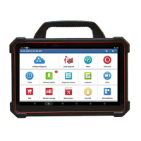
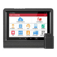
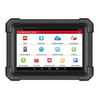
Overview of the diagnostic tool's features and capabilities.
Details of the common accessories included with the diagnostic tool.
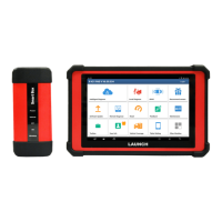
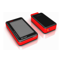
Description of the main components and their functions within the diagnostic system.
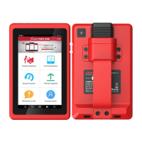
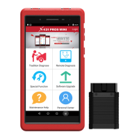
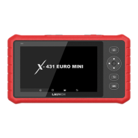
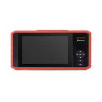
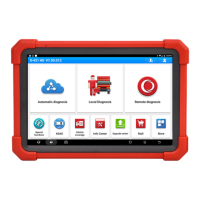
Detailed description of the tablet, its ports, and screen functions.
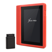
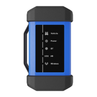
Details on the SmartLink C V2.0 device and its operational modes.
Specifications for the display tablet and SmartLink C V2.0 device.
Manage personal information and view/delete/share saved diagnostic reports.
Manage all activated Vehicle Communication Interface (VCI) devices.
Option to deactivate pairing with the VCI device.
Activate the VCI device using its serial number and activation code.
Upgrade and fix diagnostic firmware.
Manage recorded data stream sample files.
Check the status of all your orders.
Check the status of the subscription renewal card.
View and configure personal information.
Modify your login password.
Configure application settings and view software version information.
Configure measurement units (Metric System and English System).
Define your shop information including address and telephone.
Establish wireless connection for printing operations.
Clear the App cache to restart the application.
View software version information and disclaimer.
Set whether the automatic update function is ON.
Manage sub-accounts for shared access to the VCI device.
Log out the current user ID or log in to the system.
Hide or clear diagnostic software that is not frequently used.
Steps to prepare for vehicle connection, including ignition and DLC location.
Methods for connecting the VCI device to the vehicle's DLC port.
Instructions for charging the device and turning it on.
Description of the on-screen buttons and their functions.
How to adjust the screen brightness to conserve battery power.
Procedure to change the tool's system language.
Configure the standby time to save power and lock the screen.
Steps to connect the device to a Wi-Fi network for online access.
Get VIN information and guide to vehicle information without manual menu selection.
Execute menu-driven commands to diagnose the vehicle manually.
Launch instant messaging and remote diagnosis for faster repair job fixing.
Description of the remote diagnose interface elements.
Procedure to search and add partners to the friend list.
Function to send text, voice, or emoji messages to connected users.
Initiate remote diagnosis with other diagnostic tools.
Ask for remote control from a PC client technician.
Send feedback of diagnostic problems for analysis and troubleshooting.
Access previously tested vehicle's diagnostic records.
First procedure to activate the tool by registering the device account.
Overview of the main menu items after logging in.
Reset the oil service to recalculate the engine oil life interval.
Reset the brake pad after replacing the brake pad.
Reset the steering angle sensor after replacement or alignment.
Perform bi-directional tests to check Anti-lock Braking System operating conditions.
Perform gear learning for the car to turn off the Malfunction Indicator Light.
Match the anti-theft key after replacing related components.
Write injector actual code or rewrite code in the ECU to the injector.
Perform resetting operation on vehicle battery monitoring unit.
Clear PM from the DPF filter to stabilize filter performance.
Make initial settings to throttle actuators and return learned values to default.
Complete gearbox self-learning to improve gear shifting quality.
Initialize the adaptive headlamp system.
Set sunroof lock off, rain close, sliding/tilting memory, and temp threshold.
Adjust the vehicle's body height.
Learn the EGR valve after it is cleaned or replaced.
Match seats with memory function after replacement or repair.
Set size parameters of modified or replaced tires.
Activate the electronic water pump before venting the cooling system.
Perform urea reset operation after diesel exhaust treatment fluid replacement.
Reset catalytic converter learned value after NOx fault re-initialization.
Perform AC system relearn/initialization after ECU or actuator replacement.
Diagnosis and status information detection for high voltage battery.
Perform door window matching and recover power window functions.
Change the system language of the vehicle center console.
Set or learn air/fuel rate parameters.
Limit vehicle speed, disable remote key etc. for power saving.
Open or close the automatic Start/Stop function via ECU setting.
Match the intelligent cruise control module after replacement or repair.
Monitor crankshaft acceleration to determine relative power provided by each cylinder.
Perform GPF replacement or regeneration to improve fuel consumption.
Calibrate motor angle when rotor position differs from actual field position.
Reset tire pressure and turn off the TPMS indicator light.
Perform read-write functions for vehicle key, EEPROM, MCU, and ECU data.
Update diagnostic software and applications on the tool.
Instructions for updating frequently used vehicle software.
Renew software subscription when it is due or expires.
Calibrate camera-based & radar-based driver assistance systems.
Configure tablet as TPMS activation & diagnostic tool.
Diagnose and simulate vehicle sensor faults.
Measure physical parameters like voltage, resistance, frequency.
Fix battery detection faster and easier.
Check unseen parts of engine, fuel tank, braking system.
Perform read-write functions for vehicle keys and ECU data.
Quickly judge faults on automotive electronic equipment and wiring.
Frequently asked questions about the diagnostic tablet's operation.
Tips for saving power on the diagnostic tablet.
Troubleshooting steps for communication errors with the vehicle ECU.
Troubleshooting steps for failure to enter the vehicle ECU system.
Procedure for performing a factory reset on the tablet.
Steps to download the diagnostic app after a tablet reset.
Information regarding network conditions and delay for SmartLink Diag.
Required network broadband and conditions for remote SmartLink Diag.
Explanation of network delay states (Green, Yellow, Red) on the SmartLink C screen.
Possible reasons for long network delay and troubleshooting tips.
Explanation why some old vehicles might not be compatible with the system.
Determining if re-ignition is necessary for detailed analysis after OBD diagnosis.
| RAM | 3 GB |
|---|---|
| Display | 10.1-inch touchscreen |
| Battery | 7000 mAh |
| Weight | 1.5 kg |
| Storage | 32 GB |
| Connectivity | Wi-Fi, Bluetooth |
| Special Functions | Coding |
| Vehicle Coverage | Over 100 brands |
| Supported Protocols | CAN |
| Dimensions | 30 mm |
| Operating System | Android |