6
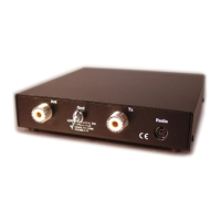
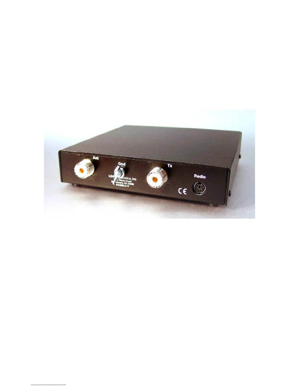
On the back panel, there are four connectors:
• RF input (marked “TX”, standard SO-239 socket)
• Antenna connector (marked "Ant", standard SO-239 socket)
• Interface jack (marked "Radio") for connecting the control cable to the IC-7000 or other
compatible transceiver
• Ground connector (wing nut)
 Loading...