Do you have a question about the LDG AT-1000 and is the answer not in the manual?
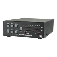
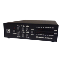
Introduces the AT-1000's front panel, including pushbutton switches and the cross-needle meter.
Explains how the tuner's meters indicate various status and information states through bounces.
Describes how to access special functions like version display or memory clearing on startup.
Details the function of each front panel button and its corresponding meter feedback during operation.
Step-by-step guide on how to tune the antenna using the AT-1000 and monitor performance.
Explains how the AT-1000 stores tuning parameters and uses memory for faster tuning cycles.
Discusses how amplifier rollback circuits interact with the AT-1000 tuning process.
Provides methods for manual tuning adjustments when automatic tuning results in high SWR.
Explains fundamental concepts of impedance, reactance, and Ohm's Law in RF circuits.
Discusses characteristic impedance, mismatch, and SWR in radio systems.
Details the L network design using toroidal inductors and toroidal capacitors for tuning.
Explains the Bruene circuit variation used for measuring forward and reflected power.
| Type | Automatic Antenna Tuner |
|---|---|
| Input Impedance | 50 Ohms |
| Memories | Up to 100 |
| Frequency Range | 1.8 to 54 MHz |
| SWR | 1:1 or better |
| Voltage Standing Wave Ratio | 1.5:1 or better |