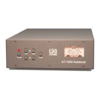
The LDG AT-1000
In 1995 LDG pioneered a new type of automatic antenna tuner. The LDG design uses banks of fixed
capacitors and inductors, switched in and out of the circuit by relays under microprocessor control. A built-
in SWR sensor provides feedback; the microprocessor searches the capacitor and inductor banks, seeking
the lowest possible SWR.
The tuner is a “Switched L” network consisting of series inductors and parallel capacitors. LDG chose the
L network for its minimum number of parts and its ability to tune unbalanced loads, such as coax-fed
dipoles, verticals, Yagis; in fact, virtually any coax-fed antenna. Using seven toroidal inductors, the total
inductance ranges from 0 to 10 µH. Each inductor’s value is selected to provide 128 different
combinations, with a resolution of 0.08 µH. The inductors are switched in and out of the circuit by relays
controlled by the microprocessor. An additional relay switches between high and low impedance ranges.
The inductors are wound with #16 wire on 2” toroid forms. Using seven 2,500 volt capacitors, the total
capacitance ranges from 0 to 1250 pF. Each capacitor’s value is selected to provide 128 combinations, with
a resolution of 10 pF. The capacitors are connected to ground with the seven inductor relays. Another relay
switches the entire capacitor bank to the input or output side of the inductor. This switching allows the AT-
1000 to automatically handle loads that are greater than 50 ohms (high setting) and less than 50 (low
setting). All of the relays are SPDT types sized to handle up to 1,000 watts SSB (500 watts key down).
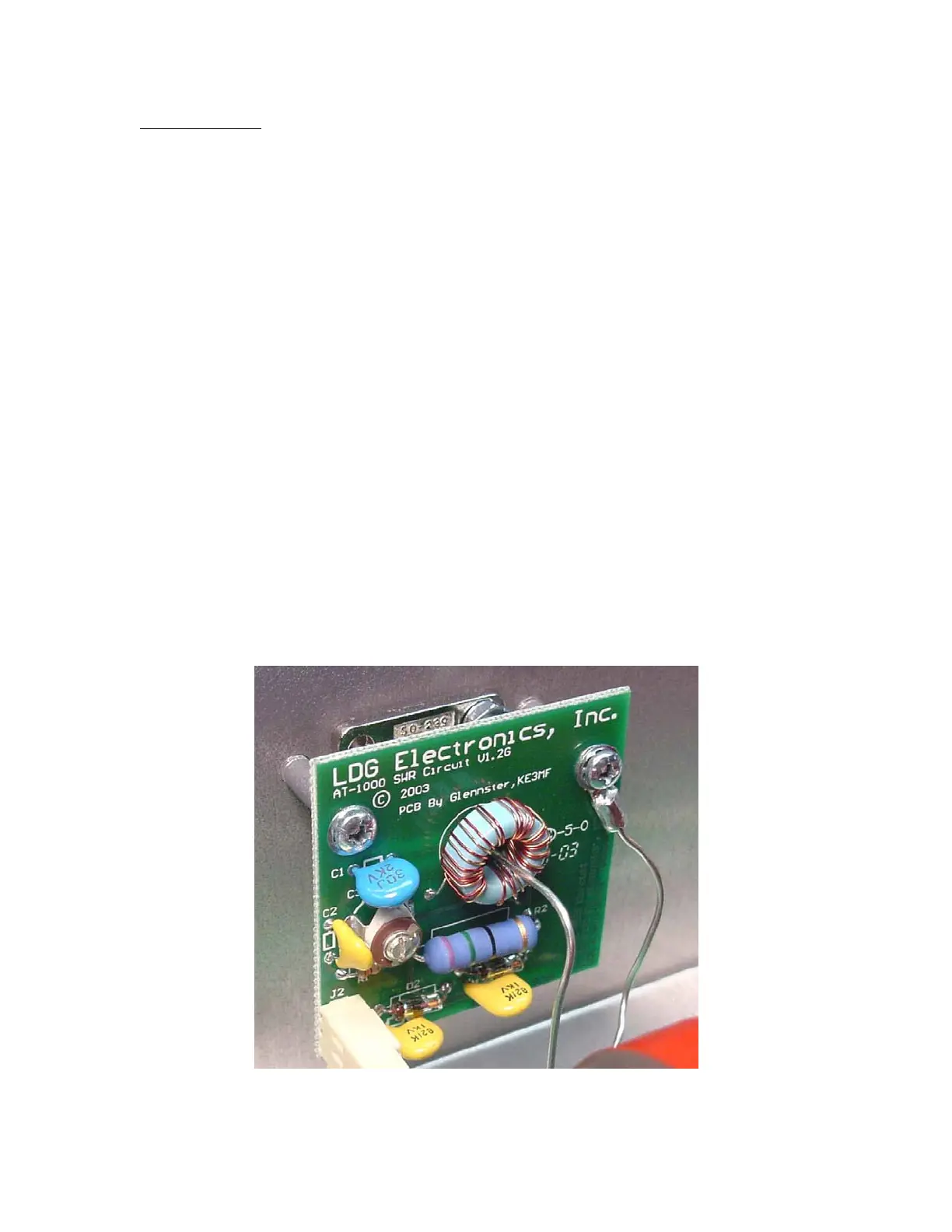
The SWR sensor is a variation of the Bruene circuit. This SWR measuring technique is used in most dual-
meter and direct-reading SWR meters. Slight modifications were made to the circuit to provide voltages
(instead of currents) for the analog-to-digital converters (ADCs) that provide signals proportional to the
forward and reverse power levels. The single-lead primary through the center of the sensor transformer
provides RF current sampling. Diodes rectify the sample and provide a dc voltage proportional to RF
power. Variable resistors calibrate the FORWARD and REVERSE power levels. Once adjusted, the
forward and reverse power sensors produce a calibrated DC voltage proportional to the forward and reverse
RF power levels. These two voltages are read by the ADCs in the microprocessor. Once in a digital format,
the they are used to calculate SWR in real time.
12
 Loading...