D
D
C
C
S
S
8
8
1
1
0
0
V
V
2
2
D
D
i
i
g
g
i
i
t
t
a
a
l
l
D
D
C
C
S
S
e
e
r
r
v
v
o
o
D
D
r
r
i
i
v
v
e
e
r
r
M
M
a
a
n
n
u
u
a
a
l
l
R
R
e
e
v
v
1
1
.
.
0
0
Tel: (86)755-26434369 34 Website: www.leadshine.com
achieved, integral gain can be added to improve stiffness. It is best to use a step
command with the profiler enabled as a reference signal during tuning.
Driver tuning is a multi-step process that involves proper tuning of up to three
different servo loops, namely current loop, velocity loop and position loop. You can
either tune the position loop around the velocity loop, or around the current loop.
Generally, it is much easier to tune a position loop around a velocity loop because
only the proportional gain is needed. When tuning position around the current loop, a
high derivative gain may be necessary on top of both proportional and integral gains.
For most of the DCS810V2 drivers have been being sold to the customers with
Leadshine’s DCM5xxxx DC servo motors, Leadshine will tune the current loop
before sending drivers out of the factory. Most of customers just need to tune the
position loop parameters with the standard version if they use the drivers with
Leadshine’s DCM5xxxx DC servo motors. If you use the DCS810V2 with DC servo
motors from other manufacturers and current loop tuning is needed. Please use
ProTuner to tune the current loop at first.
Follow the steps below for tuning the driver with the ProTuner.
Current Loop Tuning Example
If user uses Leadshine DCM series motor, they don’t need to tune the current loop
parameter. But if other brand motor is selected, please contact Leadshine for the
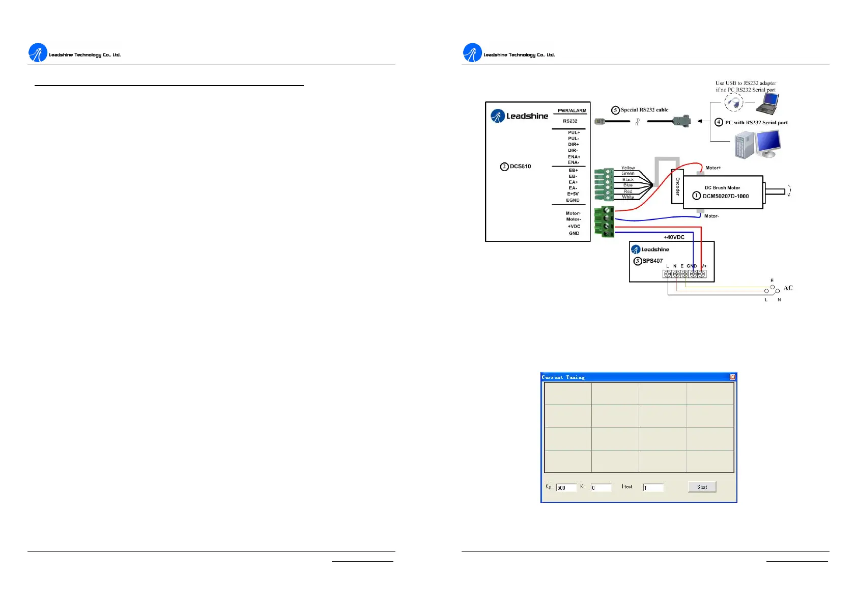
password for current loop tuning.(654321) Below is an example to show the tuning
procedure of current loop based on Leadshine DCM50207D-1000. See
Figure 6-19 for connection information and other necessary component.
(DCM50207D-1000 specification:
0.35Nm@2900RPM, Phase resistance=0.9Ohm
Phase Inductance=1.6mH, Encoder Lines = 1000)
D
D
C
C
S
S
8
8
1
1
0
0
V
V
2
2
D
D
i
i
g
g
i
i
t
t
a
a
l
l
D
D
C
C
S
S
e
e
r
r
v
v
o
o
D
D
r
r
i
i
v
v
e
e
r
r
M
M
a
a
n
n
u
u
a
a
l
l
R
R
e
e
v
v
1
1
.
.
0
0
Tel: (86)755-26434369 35 Website: www.leadshine.com
Figure 6-19: Connections in tuning example
Step 1: See figure 6-20. Set I-test 1 and begin the tuning with small Kp and zero Ki.
Here we give Kp 500. Please hit the “Enter” key after entering in the number.
Figure 6-20: Initial value for Kp, Ki and I-test for current loop tuning