D
D
C
C
S
S
8
8
1
1
0
0
V
V
2
2
D
D
i
i
g
g
i
i
t
t
a
a
l
l
D
D
C
C
S
S
e
e
r
r
v
v
o
o
D
D
r
r
i
i
v
v
e
e
r
r
M
M
a
a
n
n
u
u
a
a
l
l
R
R
e
e
v
v
1
1
.
.
0
0
Tel: (86)755-26434369 8 Website: www.leadshine.com
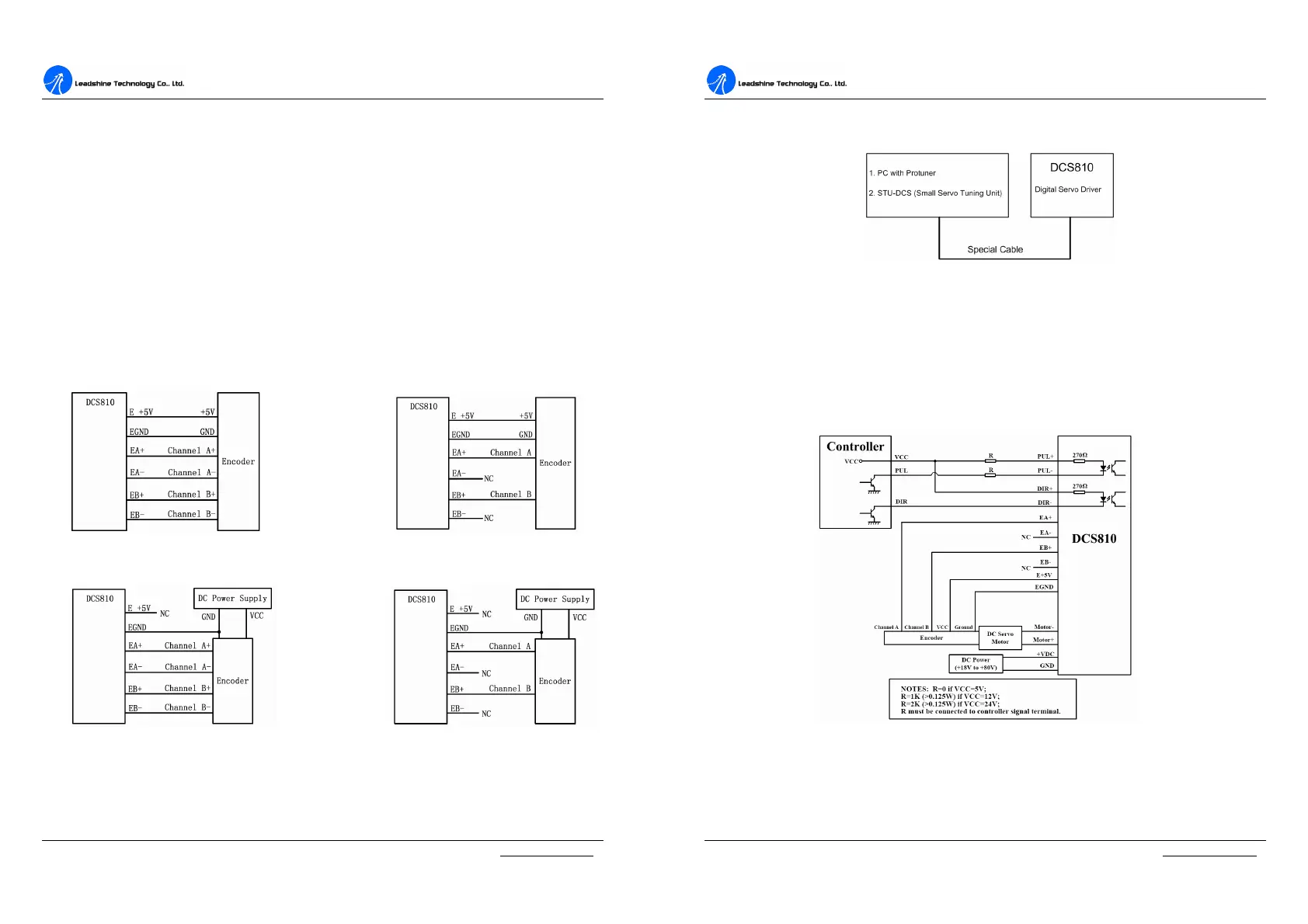
Encoder Connections
The DCS810V2 can accept encoder input from either differential or single-ended
encoders. Differential encoders are preferred due to their excellent noise immunity.
The connections for a single-ended encoder are identical to a differential encoder
except that no connections should be made to channel A- and channel B-. (The A-
and B- lines are pulled up internally to +2.5V). Note that twisted-pair shielded
cabling provides the best immunity in electrically noisy environments.
If the encoder drains less than 50mA, the DCS810V2 can supply the encoder
directly, and connect it as Figure 3-4 or Figure 3-5. If the encoder drains more than
50mA, use an external DC supply and connect it as Figure 3-6 or Figure 3-7.
Figure 3-4: The DCS810V2 supplies the Figure 3-5: The DCS810V2 supplies
the differential encoder directly single-ended encoder directly
Figure 3-6: Using external DC power supply Figure 3-7: Using external DC power to
to supply the differential encoder supply the single-ended encoder
D
D
C
C
S
S
8
8
1
1
0
0
V
V
2
2
D
D
i
i
g
g
i
i
t
t
a
a
l
l
D
D
C
C
S
S
e
e
r
r
v
v
o
o
D
D
r
r
i
i
v
v
e
e
r
r
M
M
a
a
n
n
u
u
a
a
l
l
R
R
e
e
v
v
1
1
.
.
0
0
Tel: (86)755-26434369 9 Website: www.leadshine.com
RS232 Interface Connection
Figure 3-8: RS232 interface connection
Typical Connections
Two typical connections of the DCS810V2 are shown as Figure 3-9 and Figure 3-10.
Please consult “Control Signal Connections” and “Encoder Connections” for more
information about controller and encoder connections.
Figure 3-9: Typical connection (Open-collector control signal and single-ended encoder.)