ENGINE BLEED-AIR
CONDITIONING AND
DISTRIBUTION
GENERAL
A detailed description of the air supply is pro-
vided in Chapter 9 of this manual.
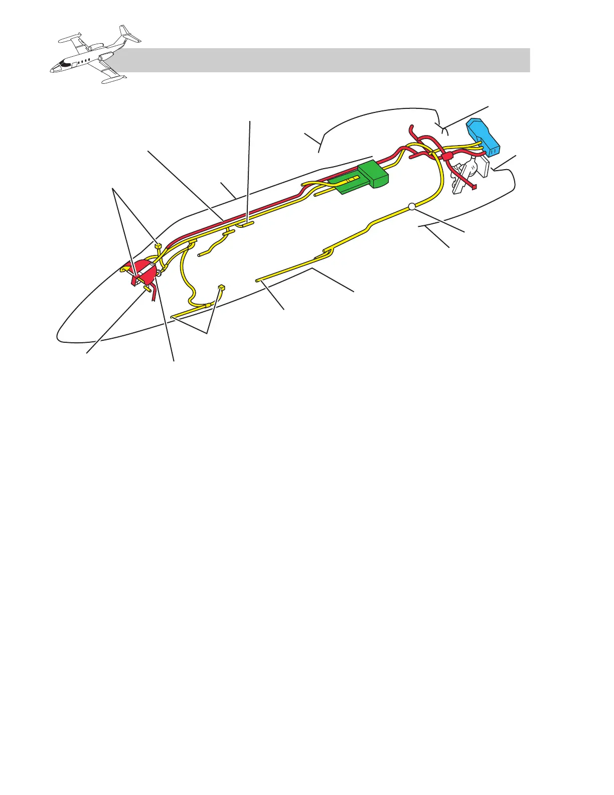
Engine bleed air is supplied to the bleed-air
manifold in the tail compartment and is then
routed through the flow control valve to the
heat exchanger. The air is then routed through
the air distribution ducts to the cabin and
cockpit. There are three systems divided as
follows: airplanes SNs 24-350 and 25-227
and subsequent; SNs 24-230 through -340 and
SNs 25-003 through 25-226; and SNs 23-003
through 24-229.
These systems differ in the manner the bleed
air is cooled, how the hot air bypass valve is
controlled, and in the switches that control the
flow control valve.
AIR-CONDITIONING SYSTEM
(SNs 24-350 AND 25-227 AND
SUBSEQUENT)
Figure 11-2 illustrates the air-conditioning
system.
LH and RH Bleed-Air
Shutoff Valves
Two bleed-air shutoff valves are installed in
each duct to the bleed-air manifold in the tail-
cone and are controlled by the respective LH
and RH AIR BLEED switches on the control
panel. In the OFF position, all bleed air is
shut off from the respective engine to the
bleed-air manifold. In the ON position, the
valve is open and permits bleed air to enter the
bleed-air distribution system.
Bleed-Air Manifold
The bleed-air manifold is essentially an
insulated metal duct which serves as a
collection point for bleed air from either or
both engines.
11-2
FOR TRAINING PURPOSES ONLY