Operation
The Freon system may be operated on the
ground or in flight below 18,000 feet (15,000
feet on Lear 23 airplanes). When the control
switch is placed in the COOL SYS position,
28 VDC is applied to the compressor motor and
the cabin blower through control relays. These
relays allow motor operation only if an airplane
generator or a GPU is supplying electrical
power and neither START–GEN switch is in
the START position.
The control switch should be in the OFF po-
sition during engine start to prevent over-
loading th 275-ampere battery charging bus
current limiters when the START–GEN switch
is placed to GEN. It is recommended to wait
until the generator load is below 150 amperes
per generator before turning the Freon system
switch to the COOL position.
NOTE
For maximum effectiveness on the
ground, the AIR BLEED or CAB AIR
switch should be turned off when the
engines are running.
Manually operated diverter doors installed in the
air ducts from the evaporator may be positioned
to direct some of the cool air into the baggage
compartment.
When the control switch is placed in the FAN
position, 28 VDC is applied to the cabin fan
which circulates only the cabin air. The fan
may be used at any altitude.
AUXILIARY HEATING SYSTEM
(OPTIONAL) (NOT AVAILABLE
ON SNs 23-003
THROUGH 24-129)
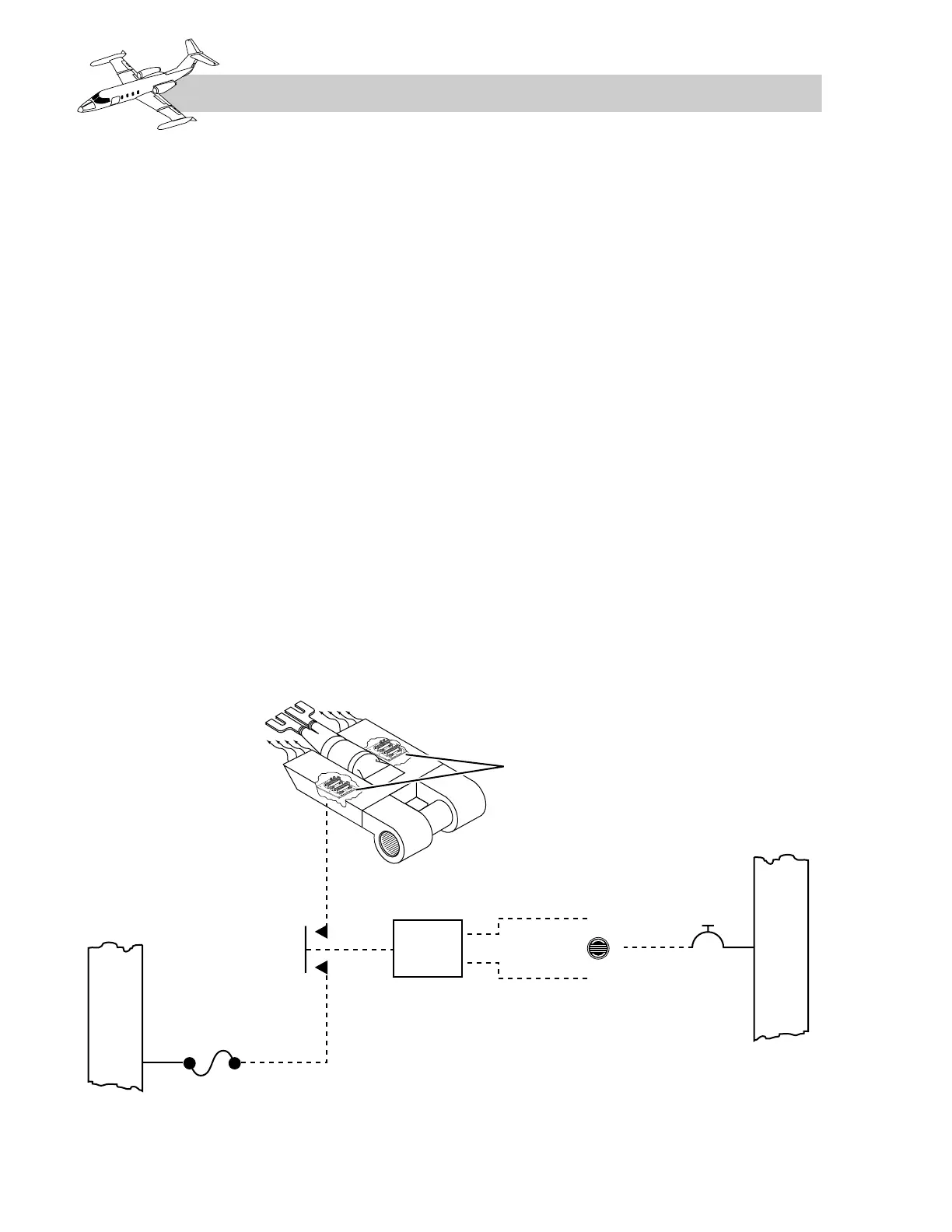
The auxiliary cabin heat system (Figure 11-19)
may be used in flight or on the ground and must
be powered by either a GPU or an engine gen-
erator. The system consists of two heater circuits
with a three-position switch (Figure 11-20) on
the copilot’s subpanel. Each heater circuit con-
sists of two heater elements wired in parallel
using the cabin fan for air circulation. The
heater elements are located in the evaporator
assembly above the baggage compartment
(Figure 11-21).
11-16
FOR TRAINING PURPOSES ONLY