LANDING–TAXI LIGHTS
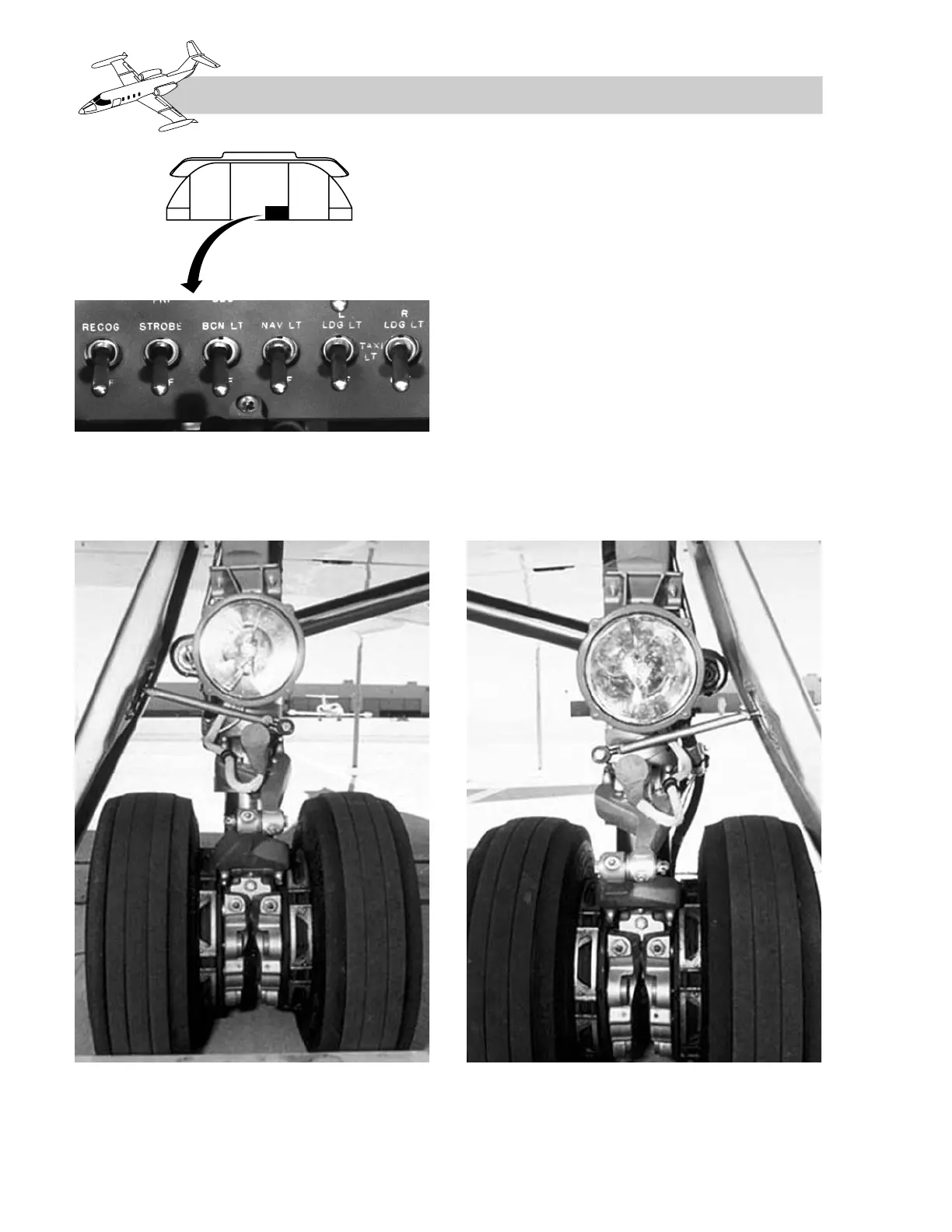
The landing light system consists of one 450-
watt lamp mounted on each main landing gear
strut (Figure 3-8), one 20-amp current limiter
for each side, relays, dimming resistors, and
the L and R LDG LT switches. The L and R
landing light switches have three positions:
OFF, TAXI LT, and LDG LT. DC power to op-
erate the relays comes from the left and right
main buses, respectively.
Setting the L or R LDG LT switch to TAXI LT
closes a relay which shunts DC power from the
respective generator bus through a resistor
which limits current to the lamp element.
Moving the switch to LDG LT closes a second
relay, allowing current flow to bypass the re-
sistor, thereby increasing the brightness of the
lamp. The 20-amp current limiters protect the
3-6
FOR TRAINING PURPOSES ONLY