GENERATORS AND
REGULATORS
Generators
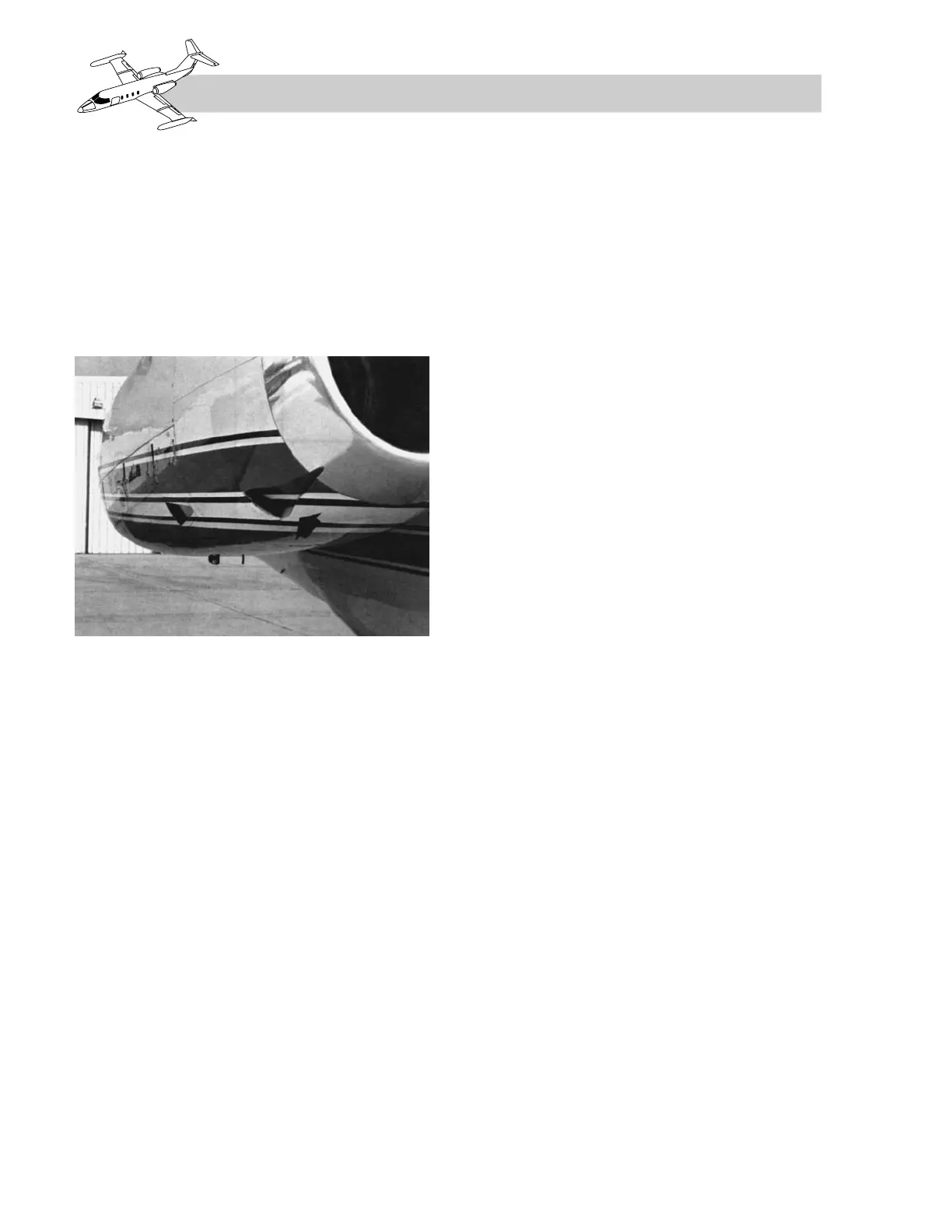
Two independent, engine-driven DC genera-
tors, rated at 30 volts, 400 amperes, are pro-
vided to supply the airplane with DC power.
The generators are air cooled by ram air from
a scoop on the engine nacelle (Figure 2-5).
Generator Control Panel
The generator control panel, installed in the
tailcone, serves as the generator control unit
for the DC electrical system. The generator
control panel incorporates the battery, exter-
nal power, right and left generator control,
overvoltage control, and equalizer circuit re-
lays. Battery, external power, and generator
outputs are connected to the generator control
box which distributes DC power through cur-
rent limiters and circuit breakers to the vari-
ous electrical systems.
Voltage Regulators
Two solid-state voltage regulators installed in
the tailcone maintain a constant output volt-
age under varying engine speeds and load
conditions. The voltage regulator is factory-
adjusted, and no adjustment is allowed. The
design of the regulators precludes voltage drift
due to temperature. Each regulator is set to 28.5
±0.3 VDC.
Should generator output exceed 32 VDC, a
circuit within the voltage regulator completes
a ground circuit and reduces generator output
to zero.
Controls
The generator switches (Figure 2-6) located
on the lower portion of the instrument panel
have three positions labeled “OFF,” “START,”
and “GEN.” OFF position deenergizes the
starter-generator. START position energizes
the engine start cycle. GEN position supplies
voltage to the generator relay, and through
the voltage regulator, to the field windings, en-
ergizing the generator to supply power to the
airplane electrical system.
Generator Reset Switches
Two generator reset switches, one left and one
right, are installed on the switch panel adja-
cent to its respective generator switch. When
in the RESET position, contacts complete a
ground circuit to reset the respective genera-
tor overvoltage relay.
Warning System
L GEN and R GEN warning lights (Appendix
B) are installed on the glareshield. The warn-
ing lights illuminate if a generator has failed
or the switch is in OFF.
Indicators
A DC ammeter is installed on the center instru-
ment panel for each generator (Figure 2-7). The
ammeter indicates the load being carried by
the respective generator. The ammeter red line
is 400 amperes and has a yellow arc from 300
to 400 amperes. The limit when OAT is 60°F
or above is 300 amperes.
A single DC voltmeter indicates DC voltage
present on the battery-charging bus. The DC
voltmeter red line is 35 VDC.
2-6
FOR TRAINING PURPOSES ONLY