OPERATION—AIRPLANES
WITH CENTURY III WING
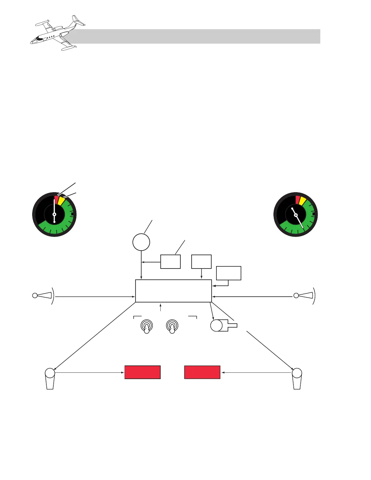
As airplane angle of attack increases, the vane-
operated transducers feed a voltage signal into
the computer/amplifier, along with flap position
and altitude information (closing of the altitude
switches at 22,500 feet increases the stick pusher
actuation point by approximately 15 knots above
airplane stall speed). The computer/amplifier
sums the signals and drives the pointer of the
ANGLE OF ATTACK indicators accordingly
(Figure 15-14).
If angle of attack increases until airspeed is 7%
above pusher actuation, the red L and R STALL
lights flash, the indicator pointer enters the yel-
low segment, and the stick shakers actuate. If
angle of attack continues to increase until air-
speed is approximately 3 knots above airplane
stall speed, the autopilot disengages and the
stick pusher applies nosedown elevator.
Testing of the system is accomplished on the
ground with the stall warning test switch on the
center pedestal. Holding the switch to R TEST
causes the pointer on the right ANGLE OF
ATTACK indicator to sweep across the green
segment. As the pointer enters the yellow seg-
ment, the right shaker actuates and the R STALL
light flashes. As the pointer sweeps into the red
segment (STALL lights on steady, airplanes with