WR6K-OM-E Rev A ISSUED: October 2003 389
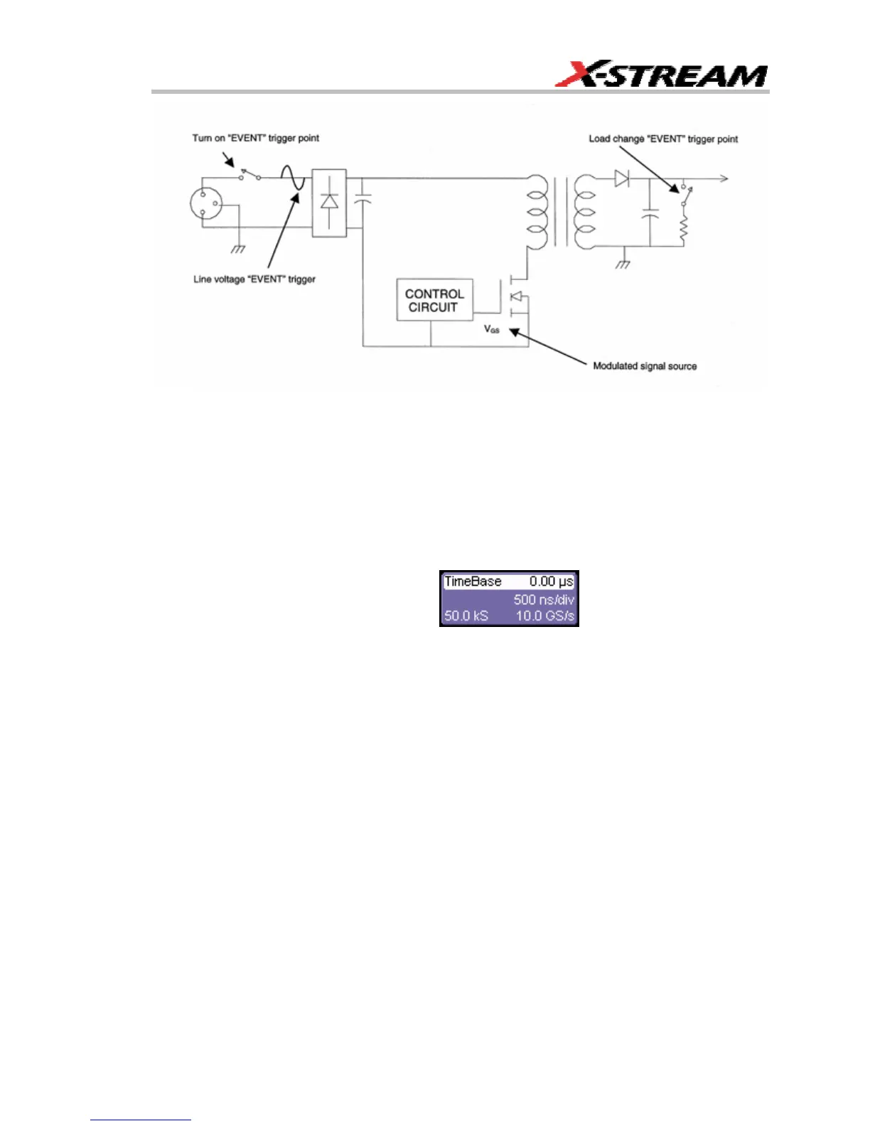
Typical connections to the circuit under test for acquiring a source of the feedback modulation and various
EVENT trigger sources.
Trigger Setup – The Event Trigger
1. Determine the event around which the acquisition of an extended signal modulation
record will be required. Triggering the acquisition of the modulated signal on these events
can test the circuit’s response to events such as line voltage change, turn-on, turn-off,
and load change. Typical trigger points are illustrated in the figure above. In the example
used here, the acquisition is triggered as the power supply’s 5 V supply load changes
from maximum to minimum. Presetting the trigger of such an event will make the final
modulation measurement setup easier.
2. Touch the Timebase descriptor label
and set the time/division,
trigger delay, and trigger level for the event trigger channel to obtain a display similar to
that shown above. If the modulated signal is to be acquired as the result of a one-time
event such as turn-on, test the event trigger for satisfactory operation in SINGLE trigger
mode. In this example, Channel 3 is used to acquire the load change signal, and the
DSO is set up to trigger from this channel. Other channels or the DSO’s EXT trigger input
also could be used for this purpose.
 Loading...


