Do you have a question about the LeCroy 9300C Series and is the answer not in the manual?
Covers inspection of scope packaging contents against packing list/invoice and identifies contact for missing/damaged items.
Details the oscilloscope's series standard capabilities, including ADC, channel configurations, and sampling rates.
Presents block diagrams illustrating the internal architecture and component connections of the oscilloscope.
Provides guidelines for operating environment parameters and safety symbols used on the instrument.
Explains the meaning of various safety symbols found on the instrument and in the manual.
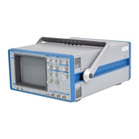
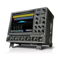
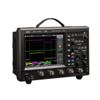
Illustrates and describes the front panel layout for two and four-channel models of the oscilloscope.
Details the four main groups of front panel controls: System Setup, CHANNELS, TIMEBASE + TRIGGER, and ZOOM + MATH.
Explains how to access and navigate through the oscilloscope's on-screen menus using buttons and knobs.
Describes System Setup controls including menu entry buttons for display, utilities, waveform store, recall, and cursors/measure.
Explains the various sections of the oscilloscope screen that display information and access commands.
Details controls for trace selection, vertical sensitivity, and offset adjustment for input channels.
Explains how to select input channel coupling (AC, DC, GND) and its effect on signal analysis.
Describes how to calibrate supplied probes and general coupling information.
Details controls for adjusting time/division, trigger level, delay, and accessing TIMEBASE/TRIGGER menus.
Explains the three sampling modes: Single-Shot, RIS, and Roll Mode, and their applications.
Details settings for sampling modes, sample clock, channel use, sequence, and record length.
Introduces trigger types (Edge, SMART) and triggering modes (AUTO, NORM, SNGL) for data capture.
Compares Edge triggers (level, coupling, slope) with SMART triggers (qualifications for glitches, patterns, etc.).
Details Edge Trigger setup including trigger source, coupling, slope, and holdoff parameters.
Explains various SMART Trigger types like Glitch, Interval, Pattern, State/Edge Qualified, TV, Exclusion, and Dropout.
Describes controls for trace selection, position, zoom, and math functions for acquired waveforms.
Explains how to use zooming and long memory for accurate timing measurements and improved time resolution.
Details standard and advanced waveform processing functions like averaging, extrema, FFT, and mathematical operations.
Explains how to apply mathematical functions to channels or reference memories and combine channels.
Covers configuration of traces for zoom/math, Multi-Zoom, and setting maximum points for math operations.
Explains how to set up FFT span and resolution, relating capture time, sampling rate, and frequency resolution.
Details display setup options including Standard/XY Mode, grids, persistence, dot join, and intensity settings.
Covers primary menus for hardcopy, time/date, GPIB/RS232, mass storage, special modes, and CAL BNC setup.
Details hardcopy settings, output devices, page feed options, and printer type selection.
Provides access to mass-storage file system controls for memory cards, floppy disks, and hard disks.
Accesses secondary menus for timebase trigger, channels, cursors measure, and firmware update.
Explains how to store waveforms to internal memory or external media in Binary or ASCII format.
Details how to recall waveforms from internal memory or external storage media to display traces.
Describes cursors as basic tools for measuring signal values in Standard, Absolute, and Relative display modes.
Explains how the instrument automatically determines signal properties using parameters in amplitude or time domains.
Details how parameters are used for Pass/Fail tests against limits or tolerance masks, including actions to take.
Describes menus for saving or recalling configurations (panel setups) to non-volatile memory or external media.
Accesses the STATUS menu for full-screen summaries of the oscilloscope's system and functional status.
Provides detailed status on sensitivity, probe attenuation, offset, coupling, timebase, and trigger status.
Details specifications for Signal Capture, including bandwidth, channels, digitizers, sensitivity, and input coupling.
Provides Signal Capture specifications for 9344C/9350C/9354C series, including bandwidth, channels, and acquisition modes.
Lists Signal Capture specifications for 9370C/9374C series, covering bandwidth, channels, sensitivity, and acquisition modes.
Details Signal Capture specifications for the 9384C Series, including bandwidth, channels, sensitivity, and offset range.
Explains how enhanced resolution filtering increases displayed trace resolution and improves signal-to-noise ratio.
Highlights how enhanced resolution filtering improves resolution and signal-to-noise ratio (SNR).
Introduces FFT analysis for revealing signal characteristics not visible in the time domain.
Explains the benefits of spectral representation for signal analysis, especially for transient signals.
Provides a general explanation of how standard parameters are computed, including top and base line determination.
Details the calculation of rise and fall times based on threshold levels and transition points.
Describes three ASCII formats (Spreadsheet, Mathcad, MATLAB) for storing waveforms for analysis packages.
Provides an example of reading a Spreadsheet format waveform file into Microsoft Excel.
| Brand | LeCroy |
|---|---|
| Model | 9300C Series |
| Category | Test Equipment |
| Language | English |
