14–1
14
CURSORS/MEASURE & Parameters
Cursors: Tools for Measuring Signal
Values
Cursors are basic, important tools for measuring signal
values.
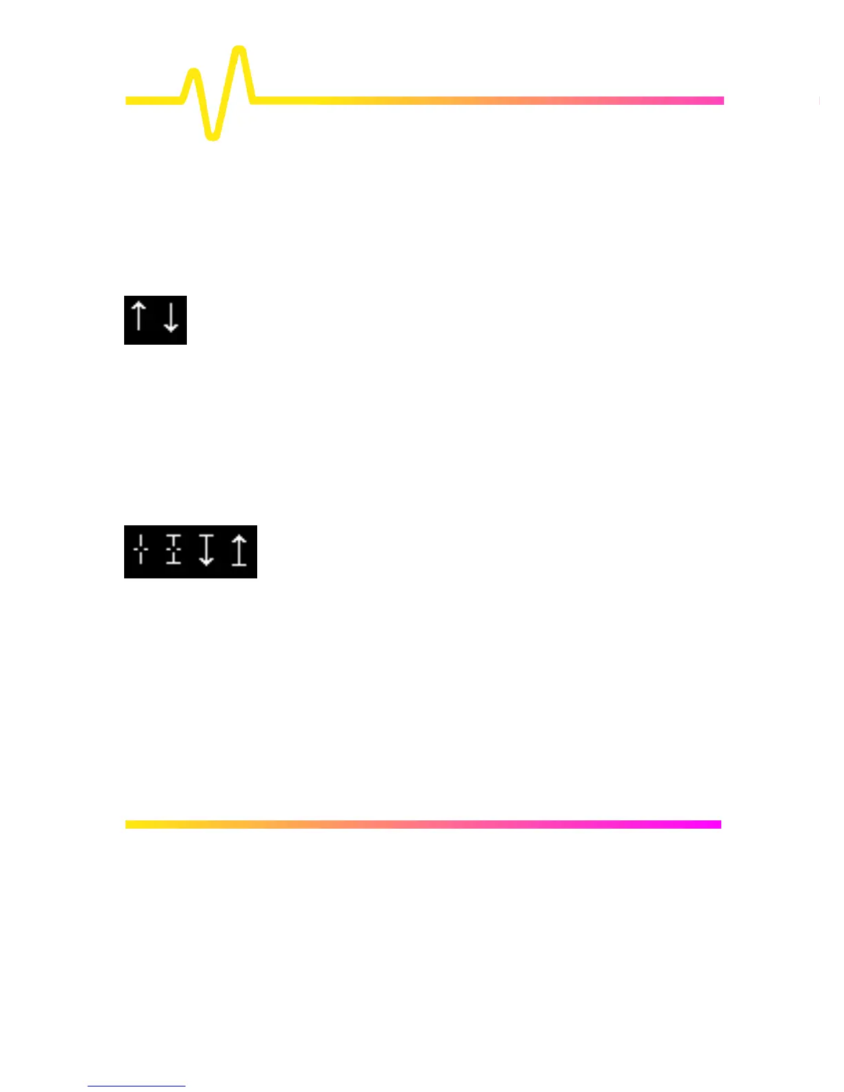
In Standard Display Mode, Amplitude, or Voltage, cursors —
broken lines or bars running across the screen — are moved up
and down the grid pixel by pixel.
Time cursors — arrows or cross-hair markers that move along
the waveform (see symbols) — can be placed at a desired time
to read the amplitude of a signal at that time, and moved to
every single point acquired.
When a Time cursor is placed on a data point, a cross-bar
appears at the tail of the arrow, and at top and bottom of the
cross-hair marker.
In Absolute Mode a single cursor is controlled. Readings for
amplitude (using Amplitude cursors) or time and amplitude
(using Time cursors) can be displayed at the cursor location.
Measured amplitudes are relative to ground; measured times to
the trigger point.
In Relative Mode, a pair of Amplitude or Time cursors is
controlled, providing readings on the difference between the two
in amplitude, or time and amplitude, respectively.
Amplitudes are shown in the Trace Label for each trace. When
Time cursors are used, the time is shown below the grid. And in
Relative Mode the frequency corresponding to the time interval
between the cursors is also displayed there.
When there are few data points displayed, Time-cursor positions
are linearly interpolated between the data points. Time cursors
move up and down along these straight-line segments.
Cursors and Persistence When using Persistence, Amplitude cursors are the same as in
Standard Display (see above). Time cursors are vertical bars
running down the screen and moving across it.

 Loading...


