Do you have a question about the LeCroy 9400A and is the answer not in the manual?
Details LeCroy's warranty terms for oscilloscope products, including repair and replacement policies.
Information on customer support services, maintenance agreements, and extended warranty options.
Addresses potential discrepancies between the manual and product due to rapid physical modifications.
Procedure for returning products for maintenance and repair, both under and out of warranty.
Guidelines for returning products for repair, including obtaining a Return Authorization Number (RAN).
Recommendation to inspect shipments immediately upon delivery and check against the packing list.
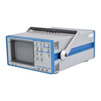
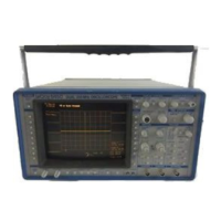
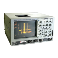
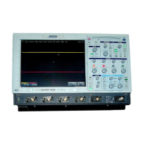
Overview of the 9400A as a high-performance digital oscilloscope for research and test applications.
Description of the 9400A's internal architecture, including the 68000 microprocessor and block diagram.
Details on the 9400A's dual ADCs, acquisition memory, and performance specifications.
Explanation of the 9400A's digitally-controlled trigger system and its various modes.
Information on the automatic calibration facility ensuring vertical and time base accuracy.
Description of the 9400A's CRT display, its interactive interface, and screen dump capability.
Overview of the 9400A's front panel layout and operation, including interactive menus.
Crucial safety information regarding power sources, grounding, and electrical hazards for operating the 9400A.
Instructions for checking and setting the correct mains voltage for the 9400A's operation.
Procedure for powering on the 9400A, including the auto-calibration sequence.
Description of the Menu Field (I) used for interacting with menus and performing operations via menu keys.
Explanation of the Time and Frequency Field (II) for displaying time differences and frequencies.
Details on the Trigger Delay Field (III) indicating pre-trigger and post-trigger settings.
Description of the Abridged Front Panel Status Field (IV) for displaying acquisition parameters.
Explanation of the Displayed Trace Field (V) showing trace identity and settings.
Details on the Message Field (VI) for displaying acquisition status or control errors.
Detailed explanation of all front-panel controls for manual operation of the 9400A.
Guide to navigating and using the 9400A's interactive menus for various functions.
Information on the fuse protection mechanism for the 9400A's power supply against shorts and overloads.
Details on LEMO connectors providing output voltages for FET probes.
Description of the rechargeable NiCd battery pack for front-panel setup retention.
Explanation of rear panel thumbwheel switch for setting addresses for GPIB and RS-232-C ports.
Information on the RS-232-C plotter connector for direct interfacing and hard copy archiving.
Overview of controlling the 9400A's functions remotely using English-like commands via RS-232-C or GPIB.
Details on the two RS-232-C ports for computer/terminal operation and plotter interfacing.
Information on the 9400A's GPIB interface for high-speed data transfer, compliant with IEEE-488.
Explanation of command syntax, format, and structure for GPIB and RS-232-C remote control.
Description of the structure and formats for transferring data blocks between the 9400A and a host computer.
Comprehensive list and explanation of all remote commands, including acquisition, display, and control functions.
Details on the binary format of waveform descriptors, including parameter addresses and bit sizes.
Explanation of the format and transmission of trigger time intervals for acquired waveforms.
Conventions for addressing data values on the screen and accessing inaccessible points via remote control.
Guidance on converting integer waveform data to volts using scale and offset parameters.
Explanation of Service Request (SRQ) generation, handling, and configuration for GPIB and RS-232-C.
Procedure for acquiring and displaying repetitive signals using basic 9400A settings.
Steps for acquiring a single pulse waveform using single-shot acquisition mode.
Guide to using trace expansion functions to magnify specific parts of waveforms.
Procedure for sequentially recording multiple single events using segmented memory.
Instructions for recording slow signals, like a 1 Hz sine wave, using manual or AUTO trigger.
How to use window triggering to capture signals exceeding specific amplitude limits.
Procedure for saving and recalling front panel configurations for quick setup recall.
Steps to store waveforms from CHAN 1 and CHAN 2 into reference memories C and D.
Using the Redefine function to expand waveforms stored in reference memories C and D.
Using the Auto-store mode to automatically save current waveforms into reference memories.
Procedure for expanding two traces simultaneously and synchronizing their intensified regions.
Guide to controlling the 9400A remotely via RS-232-C, including hardware setup and commands.
Instructions for remote control of the 9400A using GPIB, including example programs.
Steps for plotting waveforms via GPIB when computer, 9400A, and plotter are connected.
Procedure for configuring parallel polling settings using GPIB commands.
Guidance on utilizing front panel controls for optimal instrument operation and response.
Tips for achieving accurate amplitude measurements by utilizing the full dynamic range of the ADC.
Techniques for accurate time measurements, including trace expansion and cursor usage.
Explanation of the auto-calibration process for maintaining accuracy of time base and vertical gain.
Overview of the WP01 option's capabilities, including averaging, arithmetic, and functions.
Step-by-step guide for manually setting up waveform processing functions like averaging and extrema.
Information on remotely controlling WP01 functions using commands like REDEFINE and INSPECT.
Details on additional descriptor fields specific to processed waveforms, like function type and scaling units.
Explanation of the generalized system for vertical scales, including 'fgain', 'P_V', and 'P_s'.
An index listing topics related to the WP01 Waveform Processing Option by paragraph and topic.
Overview of the FFT option's capabilities, including transform size, display types, and window functions.
How WP01 functions are modified when the WP02 FFT option is installed.
Practical examples demonstrating FFT spectrum analysis using the 9400A calibrator waveform.
Remote control commands specific to FFT processing, including REDEFINE for FFT and FFT Power Average.
Practical suggestions for optimizing FFT analysis, window selection, and display types.
Definitions of key terms related to FFT processing, including aliasing, leakage, and Nyquist frequency.
Information on potential errors and warnings encountered during FFT processing and their meanings.
A table relating Nyquist frequencies to the number of points, SS/RIS mode, and time/div settings.
List of references for further reading on Fast Fourier Transforms and window functions.
An index of topics related to the FFT processing option.
Alphabetical index of all remote commands for GPIB and RS-232-C interfaces, with section references.
| Channels | 2 |
|---|---|
| Memory Depth | 1 Mpts |
| Vertical Resolution | 8 bits |
| FFT | Yes |
| Power Supply | 100-240 VAC, 50/60 Hz |
| Acquisition Modes | Peak Detect, Average |
| Trigger Modes | Edge, Pulse Width, Video |
| Input Impedance | 1 MΩ |



 Loading...