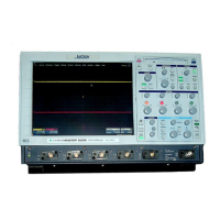
In the Common Expand mode, only the Horizontal POSITION control (39)
and the TIME MAGNIFIER control (43) act simultaneously on both the
Expand A and B signal source, while the VERT GAIN control (42) and the
Vertical POSITION control (40) act independently on each expanded
waveform.
When input signals to the 9400A are to be observed at different points
in time, it is possible to independently adjust the time difference
between the two intensified regions prior to calling the Common Expand
mode.
When the Common Expand mode is subsequently called by pressing push
buttons (7) and (4) in that order, the intensified regions for the
expansion sources may then be magnified by means of the TIME MAGNIFIER
control (43) and moved horizontally at a fixed time interval by means
of the Horizontal POSITION control (39).
The time cursors may be called by pressing push button (17) for high-
precision measurement of the time interval between the two displayed
regions.
Note that at any time the user may eliminate the time interval
separating the intensified regions by pressing RESET push button (41).
8.12 Remote Control Via the RS-232-C Port
The 9400A has been designed to permit control of all of the scope’s
functions by means of a computer/terminal. For a complete listing of
the various commands used to program the 9400A see Section 7.6.
The following examples are given to present the 9400A’s remote control
from a computer. To disable the character echoing from the 9400A issue
the following command:
<ESC> [
Preliminary Hardware Setup:
1)
2)
3)
4)
Set the thumbwheel switch (54) on the rear panel of the 9400A to
value greater than 31.
Power up the 9400A.
Connect a computer through an RS-232-C cable to the Remote port
connector (56) on the rear panel of the 9400A.
Call the RS-232-C menu by pressing push button (8). Then match the
data transfer speed and character formats of the computer and
oscilloscope (See Section 5.2.6).
8-14
Basic 9400A Waveform Measurements
and Operating Procedures
 Loading...
