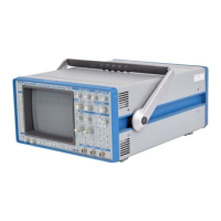
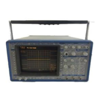
PROBE CALIBRATION (19, 20) Tocal ibrate the P901 0 Prob e, conn ect it
to the CHAN 1 or CHAN 2 BNC connector (21). Connect the probe’s
grounding alligator clip to the front panel ground lug (20) of the
oscilloscope and the tip to lug (19).
Adjust the 9400A’s front panel controls as described in Section 8.1. In
case of over- or undershooting of the displayed signal, it is possible
to adjust the P9010 Probe by inserting the small screwdriver, supplied
with the probe package, into the trimmer on the probe’s barrel and
turning it clockwise or counter-clockwise to achieve an optimal square
wave contour.
BANDWIDTH LIMIT (50) Byset ting the BAND~rlDTH LIMI T butt on to O N t he
bandwidth can be reduced from 175 MHz to 30 MHz (-3 dB). Bandwidth
limiting may be useful in reducing signal and system noise or
preventing high-frequency aliasing for single-shot events at time bases
below 50 ~sec/division.
5.1.2 Time Base
TIME/DIVISION (36) This control se lects th e time pe r division in a
1-2-5 sequence from 2 nsec to 100 sec. The time base is displayed in
the Abridged Panel Status field (IV) as well as in the Displayed Trace
field (V). The time bas~ is crystal-controlled and features an overall
accuracy better than I0
-~.
SAMPLING MODES
Three sampling modes are possible with the 9400A depending on the
time-base setting selected by the user. They are:
*
Random Interleaved Sampling (RIS)
*
Single Shot (SS)
* Roll Mode
Random Interleaved Sampling (RIS)
At time-base settings from 2 to 20 nsec/div, the 9400A automatically
uses the RIS mode for signal acquisition. Repetitive waveforms and a
stable trigger are required. Waveforms can be digitized with sampling
intervals as small as 200 psec for an equivalent sampling rate of up
to 5 gigasamples/sec.
5-4
Manual Operation
 Loading...
