VAR (28) - Verniers provide continuously variable sensitivity within
the VOLTS/DIV settings and extend the maximum vertical sensitivity
factor to up to 12.5 V/div. Variable sensitivity settings are indicated
by the ">" symbol in the lower portion of the Abridged Front Panel
Status field and the calibrated value appears in the Total V/div field
of the Panel Status menu (See Section 5.2.2). (Minimum sensitivity
achieved by rotating the vernier counter-clockwise.)
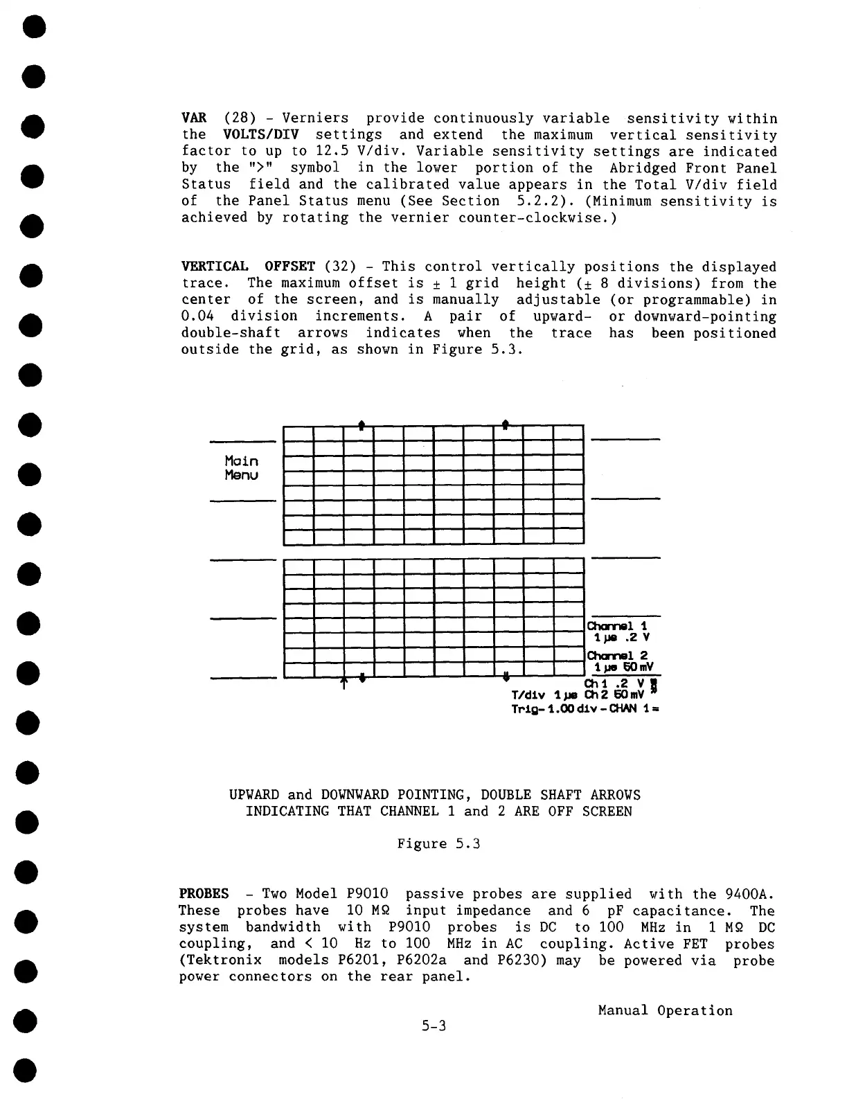
VERTICAL OFFSET (32) - This control vertically positions the displayed
trace. The maximum offset is ± 1 grid height (± 8 divisions) from the
center of the screen, and is manually adjustable (or programmable)
0.04 division increments. A pair of upward- or downward-pointing
double-shaft arrows indicates when the trace has been positioned
outside the grid, as shown in Figure 5.3.
ir
w
UPWARD and DOWNWARD POINTING, DOUBLE SHAFT ARROWS
INDICATING THAT CHANNEL 1 and 2 ARE OFF SCREEN
Figure 5.3
PROBES - Two Model P9010 passive probes are supplied with the 9400A.
These probes have I0 M~ input impedance and 6 pF capacitance. The
system bandwidth with P9010 probes is DC to I00 MHz in 1M~ DC
coupling, and < I0 Hz to I00 MHz in AC coupling. Active FET probes
(Tektronix models P6201, P6202a and P6230) may be powered via probe
power connectors on the rear panel.
Manual Operation
5-3