SCREEN DUMP button (II) - Dumps the contents of the screen to
on-line digital plotter via the 9400A’s rear panel RS-232-C interface
port or optional GPIB port to provide color or monochrome hard copy
archiving of the display. All of the screen illustrations included in
this manual were produced using the SCREEN DUMP function.
5.1.7 Cursors
Cursor measurements can be made simultaneously on up to 4 traces on the
9400A’s CRT.
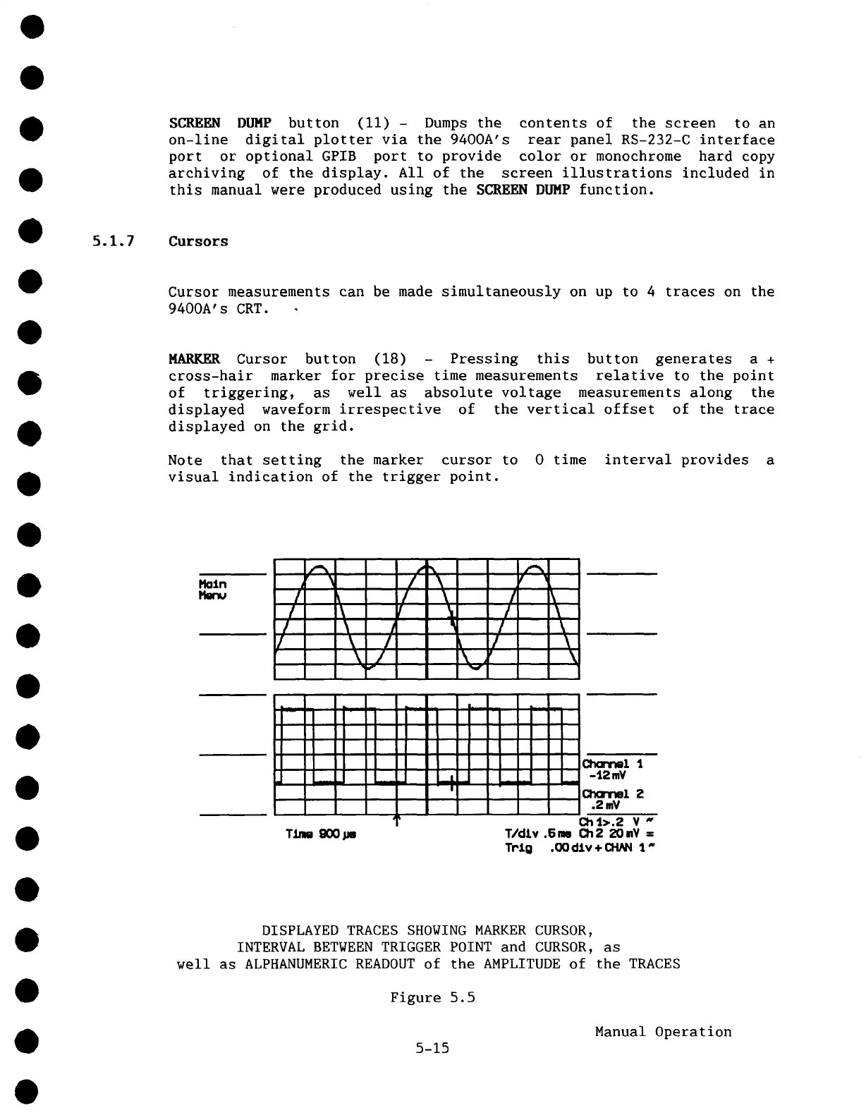
HARKER Cursor button (18) - Pressing this button generates a
cross-hair marker for precise time measurements relative to the point
of triggering, as well as absolute voltage measurements along the
displayed waveform irrespective of the vertical offset of the trace
displayed on the grid.
Note that setting the marker cursor to 0 time interval provides a
visual indication of the trigger point.
r
/ \
/
/ \ ! \
/ \
/ \
/
f
/ \
/
\
/ \
/
v
\
!
!
I
I
I ."-- -
: ." : i :
.. .
. ,
..
I I I "
i Y_i
i ,
i-i-l
’+-
. , . : :
I I .-
:
..
!!- :
.
J i,+--
: ~). 1.
-4.2 mY
l,.
Channel 2
.2mV
Ch 1>.2 V
~
T/dlv .Snm Ch2 20mY ffi
Trig .00 dlv + CHN~ 1"
DISPLAYED TRACES SHOWING MARKER CURSOR,
INTERVAL BETWEEN TRIGGER POINT and CURSOR, as
well as ALPHANUMERIC READOUT of the AMPLITUDE of the TRACES
Figure 5.5
5-15
Manual Operation