SECTION 4
DISPLAY LAYOUT
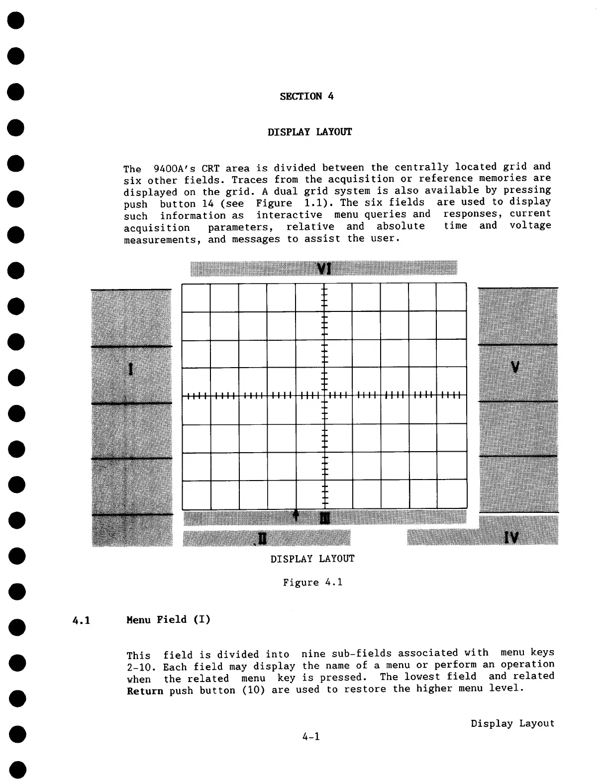
The 9400A’s CRT area is divided between the centrally located grid and
six other fields. Traces from the acquisition or reference memories are
displayed on the grid. A dual grid system is also available by pressing
push button 14 (see Figure 1.1). The six fields are used to display
such information as interactive menu queries and responses, current
acquisition parameters, relative and absolute time and voltage
measurements, and messages to assist the user.
°.
..
DISPLAY LAYOUT
Figure 4.1
4.1 Menu Field (I)
This field is divided into nine sub-fields associated with menu keys
2-10. Each field may display the name of a menu or perform an operation
when the related menu key is pressed. The lowest field and related
Return push button (i0) are used to restore the higher menu level.
4-1
Display Layout