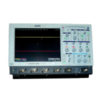
SECTION 8
BASIC 9400A WAVEFORM MEASUREMENTS AND
OPERATING PROCEDURES
The purpose of this section is to provide the user with a concise
overview of the wide range of measurement capabilities offered by the
LeCroy 9400A. While you may already be familiar with traditional
oscilloscope operation, this brief outline will help to acquaint you
with the many powerful features of the 9400A.
********
*NOTE*
********
8.1
In the following section we have chosen to set all acquisition
parameters from the Panel Status menu; however, it is not necessary to
be in this menu to make front panel setting changes. In the majority of
cases, viewing the Abridged Panel Status Field (IV) will provide all
necessary indications.
Repetitive Signal Acquisition
I.
Applying Probe Calibration Signal
1)
Connect the P9010 probe connector to CHAN 1 input (21).
2)
Connect the probe’s grounding clip to lug (20) and touch the tip
to lug (19).
3)
In the Main Menu, press the Recall PANEL push button (5).
4)
Recall the Default panel setup (9).
5)
Return to the Main Menu by pressing the Return push button (i0).
6) Call the Panel Status menu (2).
7) Set CHAN 1 Fixed VOLTS/DIV to I0 mV (27).
8)
Adjust CHAN 1VAR vernier (28) for a Total V/div of 13.0 mV.
9) Set CHAN 1 OFFSET to -50 mV (32).
i0) Set CHAN 1 COUPLING to DC 1 M9
ii) Adjust TRIGGER DELAY control (34) to 20.0~ Pre.
12) Adjust TRIGGER LEVEL control (33) to .00 division.
13) Set TRIGGER COUPLING to AC (30).
14) Set TRIGGER SOURCE to CHAN i (23).
15) Set TRIGGER SLOPE to POS (25).
16) Set TRIGGER MODE to AUTO (29).
17) Set TIME/DIV control (36) to .5 msec.
18)
Note that at this TIME/DIV setting, INTERLEAVED SAMPLING (RIS)
OFF.
19) Set BANDWIDTH LIMIT to OFF (50).
8-1
Basic 9400A Waveform Measurements
and Operating Procedures
 Loading...
