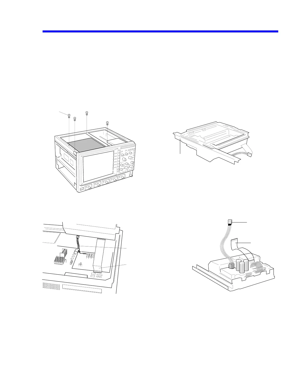
C. Removal of the Printer Assembly
Remove the upper cover.
• C1 : Remove the four M3 x 6 screws (2 on the TOP FRAME L/2 on the center frame).
• C2 : Remove the CPU J7/FFC cable.
• C2 : Remove the POWER BOARD CN6/power 3P cable.
[C1] [C3]
1
10
[C2 ] View as the rear side of the printer unit lifted [C4]
3
5
Printer
Rear
CN6/power 3P cable
J7/FFC cable
Mechanical Part & Removal 7-5
 Loading...


