Rev. D Performance Verification 5-21
!
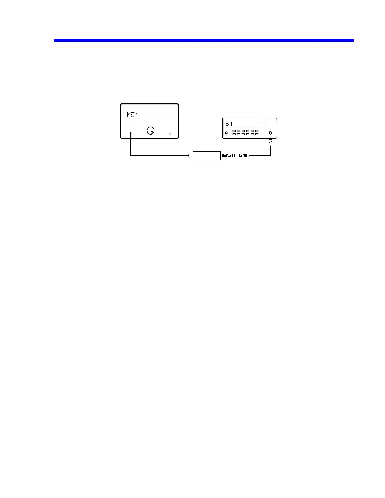
Connect a 5ns 50
Ω
BNC cable to the
RF output
of the HP8648B
generator and then through a 6dB attenuator and the necessary adapters to the
power sensor.
Figure 5-5 : Power Meter Equipment Setup
!
Set the generator frequency to
300 kHz
!
Set the power meter to the correct
Correction Factor
!
Set the generator amplitude to measure
0.200 mW
on the power meter.
!
Read the displayed
generator output amplitude
, and record it in the third
column of Table 7.
!
Repeat the above measurement for 1.1 MHz, 10.1 MHz, 100.1 MHz, 250.1 MHz
& 500.1 MHz (changing the correction factor of the power meter at each
frequency). Record the generator output amplitude readout in the third column of
Table 7 for LT37X or LT354. For LT26X, use Table 7A for frequencies of 1.1
MHz, 10.1 MHz, 100.1 MHz, 175.1 MHz & 350.1 MHz. For LT584, use Table 7B
for frequencies of 1.1 MHz, 10.1 MHz, 100.1 MHz, 250.1 MHz, 500.1 MHz &
1000.1 MHz.
!
Disconnect the
RF output
of the HP8648B generator from the
HP8482A power
sensor.
!
Connect the
RF output
of the HP8648B generator through a
5ns 50 Ohm BNC cable and a 6 dB attenuator into Channel 1.
!
Set the generator frequency to
300 kHz
.
!
From the generator, apply the
recorded
generator signal amplitude
to
Channel 1.
!
Press
Clear Sweeps
.
Power Sensor
Power Meter
Power Ref
Output
Sensor Input
Sine Wave
Generator
6
DB
6 db
 Loading...


