7-10 Mechanical Parts & Removal
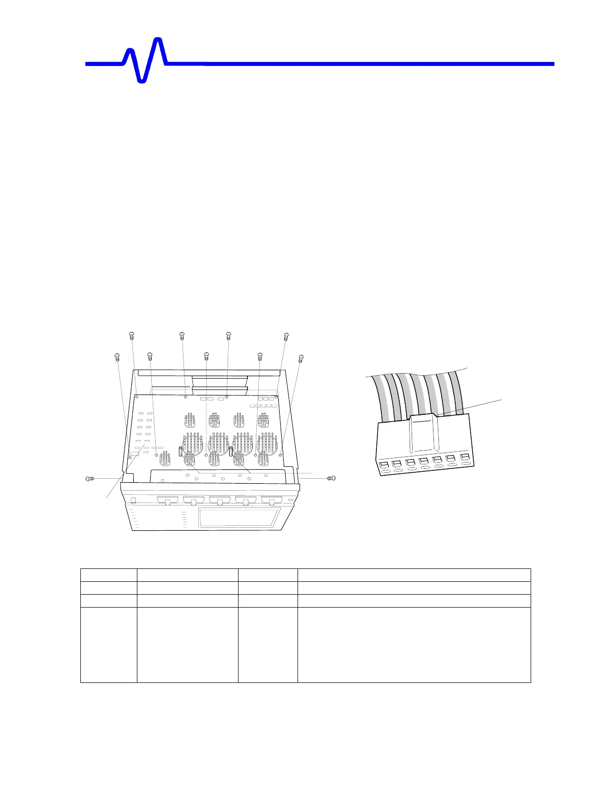
F. Removal of the Main Board
Remove the upper and bottom covers.
[Note] Remove the cables on the Main Board and next the screws on it.
• F1 a/b : Remove the four FFC cables (20J1/26pin, 20J4/22pin, 20J2/26pin,
20J3/22pin).).
• F1 a/b : Remove the Signal out connector (16J2).
• F1 a/b : Remove the 7P power connectors (21J1, 21J2, 21J3) while pressing the
stopper of 21J1 and 21J2.
• F1 a/b : Remove the two support PNC20 from the main board.
• F1 a/b : Remove the nine M3 x 6 screws (on the Main Board).
• Remove the main board by lifting its rear side slightly and sliding it rearward.
[F1a]
1
3
2
Press
21J1, 21J2
Main Board Replaceable Parts
Item Part Number Quantity Description
1 MKB130062 11.0 Screw M3x6
2 MZT902191 2.0 Metallic support PNC20
3
213025605
213025650
213025648
213025670
213025700
1.0
1.0
1.0
1.0
1.0
MAIN BOARD ASSYSee Fig [F2] LT344/344L
LT342/342L
LT322
LT224
LT364/364L

 Loading...

