9
CONTENTS
13 PARAMETER TABLES CONTINUED
“BAS” Basic menu (continued)
Code Description ACC UoM DEF Range
P.12 Step 2 function Adm OFF
=
P.13 Step 3 function Adm OFF
=
P.14 Step 4 function Adm OFF
=
P.15 Step 5 function Adm OFF
=
P.16 Step 6 function Adm OFF
=
P.17
(1)
Step 7 function Adm OFF
=
P.18
(1)
Step 8 function Adm OFF
=
P.19 Cos phi setpoint Usr 0.96
LEAD
0.50 Lead – 0.50 Lag
P.20 Alarm message language Usr ENG
ENG
ITA
FRA
SPA
POR
GER
P.01 – Value of the transformer primary current. Example: with CT 800/5, set 800. If set to OFF, after switch-on the device invites you to dene the CT and allows
direct access to the parameter.
P.02 – Value of the current transformer secondary. Example: with CT 800/5, set 5.
P.03 – Denes the phase on which the device reads the current signal. The current input wiring must correspond to the value dened for this parameter.
Accounts for all the possible combinations of parameter P.05.
P.04 – Read the CT connection polarity.
AUT = The polarity is automatically detected on switch-on. Can only be used when working with one CT and when the installation has no electricity-
generating device.
Dir = Automatic detection disabled. Direct connection.
Rev = Automatic detection disabled. Crossover.
P.05 – Denes how many and on which phases the voltage signal is read. The voltage input wiring must correspond to the value of this parameter. Accounts
for all the possible combinations of parameter P.03.
P.06 – Reference power in kVAr relating to parameters P.11 to P.18 (usually the power in kVAr of the smallest installed step), at the nominal voltage stated in
parameter P.07.
P.07 – Nominal voltage of steps.
P.08 – System working frequency:
Aut = automatic selection between 50 and 60 Hz on switch-on.
50Hz = set to 50 Hz
60Hz = set to 60 Hz
Var = variable, measured continuously and adjusted.
P.09 – Minimum time which should elapse between disconnection of a step and its reconnection, in MAN or AUT mode. During this time, the step number on
the main page ashes.
P.10 – Sensitivity on connection. This parameter denes the controller reaction speed. With a low value of P.10 regulation is fast (more accurate around the
setpoint, but with more step switching operations). With high values we have slower regulation reactions, with fewer step switching operations. The
controller time delay is inversely proportional to the demand required by steps to reach the setpoint value: wait = (sensitivity/number of steps required.
For example: with the sensitivity set to 60, if you wish to insert a step, the time is 60 s (60/1 = 60). If 4 steps are needed the time will be 15 s (60/4 = 15).
P.11 ... P.18 – Function of output relays 1 ... 8:
OFF = Not used.
1 .. 32 = Multiplication factor. These relays control steps with a power rating n times (n = 1 ... 32) the reference power dened in parameter P.06.
ON = Always connected.
NOA = alarm normally switched o. The relay is energised when an alarm with the global alarm property appears.
NCA = alarm normally switched on. The relay is de-energised when an alarm with the global alarm property appears.
MAN = the relay is energised when the device is in manual mode.
AUT = the relay is energised when the device is in automatic mode.
FAN = The relay controls the cooling fan.
A01 ... A13 = The relay is energised when the specied alarm is active.
P.19 – Cos phi setpoint (target value). Used for standard application.
P.20 – Alarm message language.
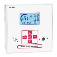
(1) Only for ALPTEC 5.2 and 8.2
 Loading...