14
CONTENTS
15 DESCRIPTION OF ALARMS
Code Alarm Description
A01 Undercompensation All the steps are connected but the cos phi is below the setpoint.
A02 Overcompensation All the steps are disconnected and the cos phi is above the setpoint.
A03 Current too low The current read by the controller is lower than the minimum possible measurement. The installation can be
at no-load.
A04 Current too high The current read by the controller is higher than the maximum possible measurement.
A05 Voltage too low The voltage measured is lower than the threshold set at P.42.
A06 Voltage too high The voltage measured is higher than the threshold set at P.41.
A07 Capacitor overload The overload current is higher than the threshold set at P.32 and P.33.
A08 Temperature too high The temperature measured is higher than the threshold set at P.39.
A09 Micro-interruption Micro-interruption on the voltage measurement input lasting more than 8 ms.
A10 Voltage THD too high The installation THD U is higher than the threshold set at P.43.
A11 Current THD too high The installation THD I is higher than the threshold set at P.44.
A12 Maintenance required The maintenance interval set at P.45 or P.54 has been exceeded. To reset, use the CMD command menu.
A13 Step fault The residual power of the indicated step is lower than the threshold set at P.40.
Code Description Enable Alarm relay Disconnection Delay
A01 Undercompensation • • 15 min
A02 Overcompensation • • 120s
A03 Current too low • • 5 s
A04 Current too high • • 120s
A05 Voltage too low • • • 0s
A06 Voltage too high • • • 0s
A07 Capacitor overload • • • 30s
A08 Temperature too high • • • 60s
A09 Micro-interruption • • • 0s
A10 Voltage THD too high • • • 5 s
A11 Current THD too high • • • 5 s
A12 Maintenance required • • 0s
A13 Step fault • • • 5 s
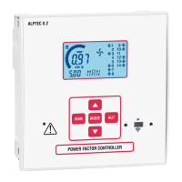
14 ALARMS
– When an alarm is generated, the screen displays an alarm icon, the alarm code and description in the language selected.
– If the navigation buttons in the pages are pressed, the scrolling message showing the alarm information briey disappears, and then
reappears after a few seconds.
– The alarms are automatically reset once the alarm conditions which generated it have disappeared.
– If there are one or more alarms, ALPTEC's behaviour depends on the properties of the active alarms.
16 “CMD” COMMAND MENU
- This menu allows you to execute one-o operations such as resetting counters, alarms, etc.
- Following the procedure outlined in the “Setting the “SET” parameters” section on page 7, go to the CMD menu.
- Press or
UT
to scroll upwards through the commands. Press
(1)
or
MA
(2)
to go back.
- Hold down for 3 seconds to conrm the command to be executed, the controller asks you for conrmation OK? on the main screen with a countdown.
- Continue pressing until the end of the countdown for denitive conrmation. Releasing the button before the countdown nishes will cancel the
command.
- Press or
UT
to return to the main menu.
- The table below indicates which commands are possible:
Code Command Access level Description
C01 Maintenance reset Usr Resets the maintenance interval
C02 Step counter reset Usr Resets the step counter
C03 Step power setting reset Adm Resets the original step power rating
C04 Step no. of hours reset Adm Resets the step no. of operating hours
C05 Max. values reset Adm Resets the previously saved maximum values
C06 Weekly Power Factor reset Usr Resets the weekly Power Factor value
C07 Default settings Adm Initialises all parameters with their default values
C08 Back up conguration Adm Makes a copy of the user settings
C09 Restore conguration Adm Loads the settings with the above backup copy
(1) Only for ALPTEC 3.2 and 5.2
(2) Only for ALPTEC 8.2
 Loading...