3
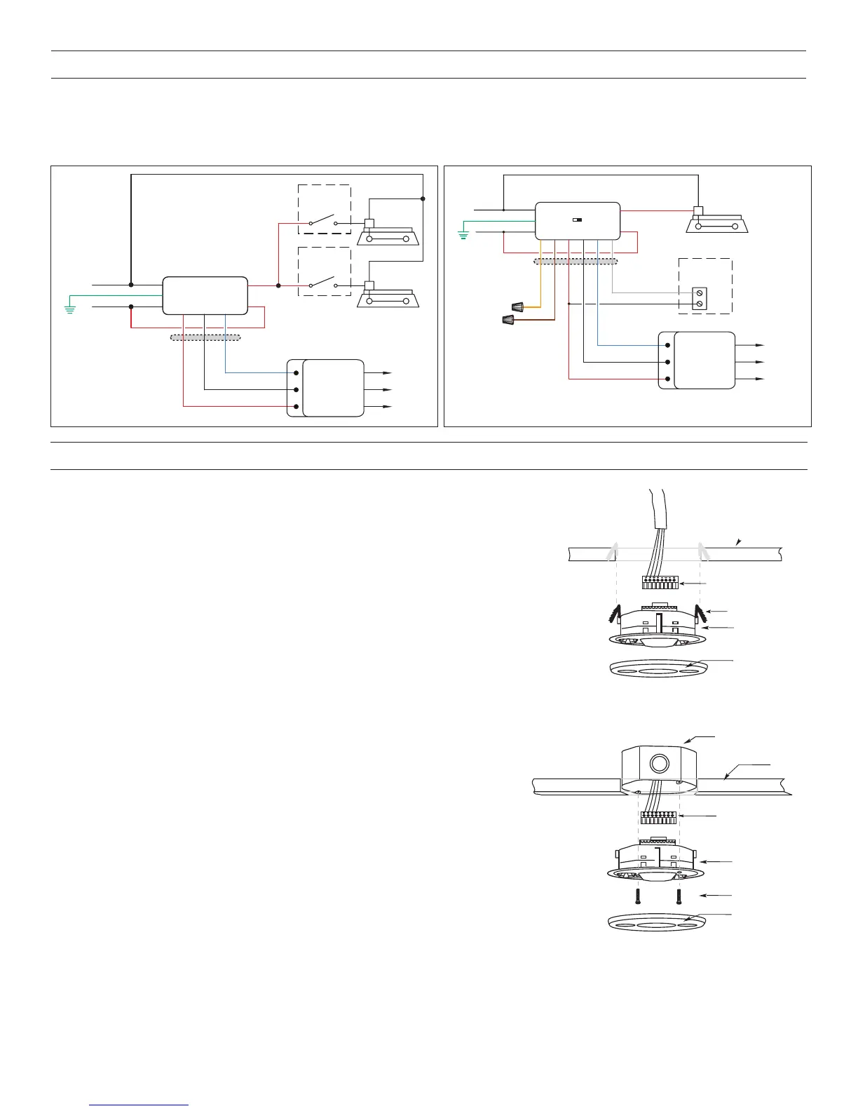
Standard wiring with two local off switches Manual-On wiring with low voltage momentary switch
Low Voltage Wires
Control Output
Common
+24VDC
Neutral
Hot
White
Black
Red
Black
Power Pack
Blue
Red
Red
Fixture
BZ-200
**Ground
*To
Additional
Sensor(s)
** BZ-200 Power Pack
must be grounded to
ensure signal integrity,
not for safety ground.
Optional
Local Off
Switch
Fixture
Optional
Local Off
Switch
DT-300/DT-305
Low Voltage
Occupancy
Sensor
Red
Red
Common
+24VDC
Control Output
Hot
Neutral
Black
White
Power Pack
BZ-250
Brown
Black
Grey
Orange
Red
Blue
Cap
Cap
COM
SW1
LVSW-101
Low Voltage
Switch Input
** BZ-250 Power Pack
must be grounded to
ensure signal integrity,
not for safety ground.
**Ground
Fixture A
(A)
DT-300/DT-305
Low Voltage
Occupancy
Sensor
*To
Additional
Sensor(s)
Auto
ON
Man
ON
Low Voltage
Wires
CONNECTING WIRES
• Care should be taken to separate high voltage power from low voltage (Class 2) control wiring.
• All connections to sensor are low voltage, Class 2.
MOUNTING THE SENSOR
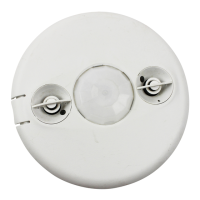
Directly to Ceiling
1. Attach the plastic spring clips to the edge of the sensor in the slots provided.
2. Cut a 3.5” to 4” round hole in the acoustic ceiling tile at the mounting location. A 3.5”
hole is recommended for a secure fit.
3. Pull the low voltage wire from the power pack to the sensor through the hole.
4. Connect the low voltage wires to the appropriate terminals on the sensor.
5. Push the sensor up through the hole until the Spring Clips hold the sensor securely in
place.
6. Snap the front cover onto the sensor.
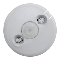
Using an Octagonal J-Box
1. Pull the low voltage wires from the power pack into the J-Box through the
conduit knockout.
2. Connect the low voltage wires to the appropriate terminals on the sensor.
3. Loosen the appliance mounting screws attached to the J-Box
4. Align the sensor in the J-Box so that the mounting screws on the box match
the key holes on the sensor’s rear housing.
5. Push the sensor up into the J -Box and twist it so that the mounting screws are
seated in the keyhole slots.
6. Tighten the two screws to secure the sensor to the J-Box.
7. Snap the front cover onto the sensor.
Rear
housing
Depluggable terminal
Front
Spring clips (2)
Ceiling Mount
Rear
housing
Depluggable
terminal
(at least 1.5" deep)
Front
Ceiling
Screws
J-Box Mount
 Loading...