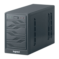
EPO push-button and phase rotation
Before switching the UPS on, make sure that:
1) the emergency power off “EPO” push-button, if installed, is not pressed. If not,
press it back to the rest position;
2) the input and output phase rotation is correct.
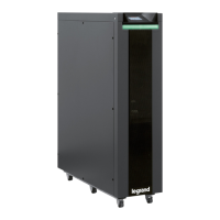
Circuit breaker BCB
Do not close the battery breaker BCB before it’s required by the front panel. Serious
damages to the UPS internal parts and/or to the battery may occur.
Wiring of the auxiliary contacts
Carry out a proper electrical installation by wiring the auxiliary contacts of the external
manual bypass, output and battery isolators to the dedicated terminals on board the
UPS. This will allow the control logic to acquire the status of the switches and guide
the operator during the start-up and manual bypass procedures.
No. LCD DISPLAY ACTION OPERATING CHECKS
1 BLANK
Close RCB
After operating switch RCB the pre-charging
phase of the capacitive bank will start. The
control logic will be started and the front
panel is activated.
2 BOOT LOADER
“BOOT” phase where the UPS firmware can
be updated following the appropriate
procedure. All the LED’s on the front panel
are on.
3 EEPROM READING
Reading of the configuration parameters
stored in the EEPROM.
All the LED’s on the front panel are off.
4 EEPROM PARAM.
SENDING
Sending of the configuration parameters
stored in the EEPROM.
All the LED’s on the front panel are off.
5 PLEASE WAIT
6 UPS START UP
PLEASE WAIT
UPS start-up. LED #1 is on - input voltage
present.
7 RECTIFIER START UP
PLEASE WAIT
The IGBT rectifier bridge starts to modulate;
VDC voltage reaches the nominal value.
LED #3 is lit green: DC voltage present.
 Loading...