5
PANEL CIRCUIT BOARD LAYOUT AND CONNECTION
The LMCP contains two types of circuit boards:
• The LMPI board is the main controller board and is connects to the Local DLM network and to other panels or other BACnet
devices (see Fig. 3a and 3b).
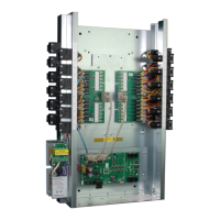
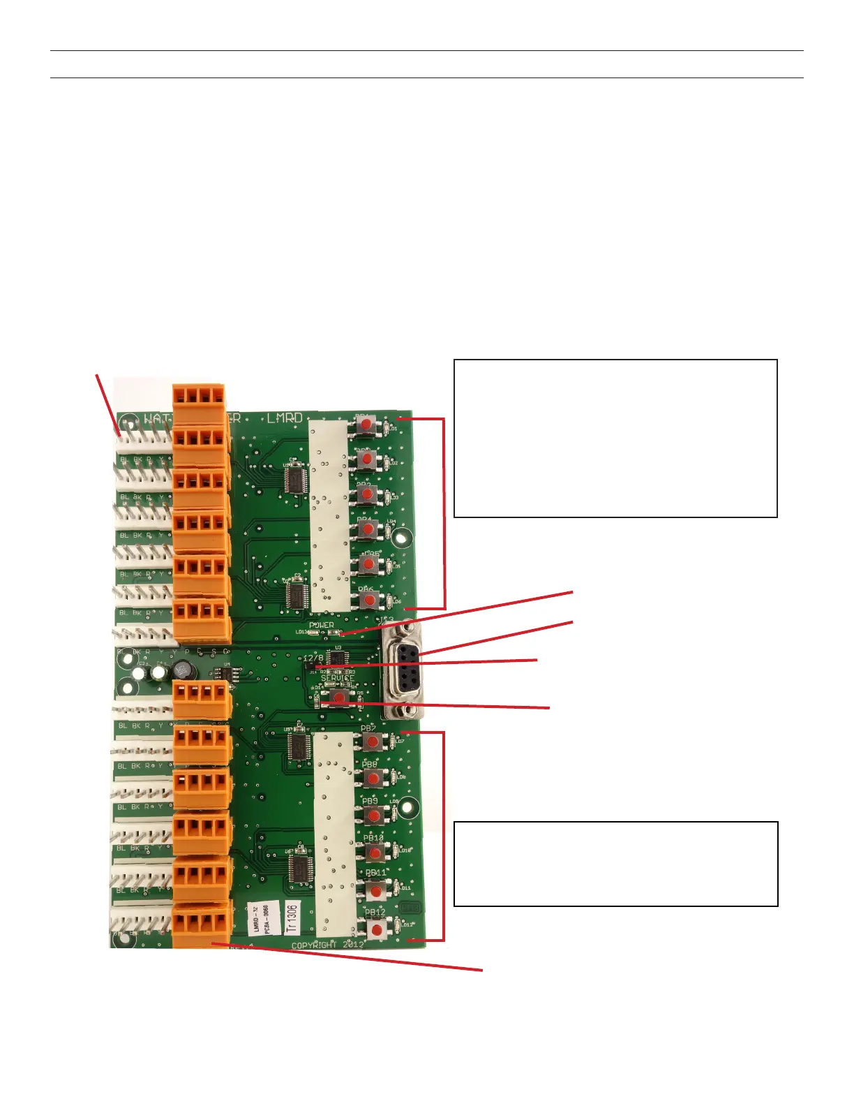
• The LMRD board is the relay control board. (see Fig. 2). A single board can control 12 relays.
NOTE: The LMCP-8 contains a single LMRD board (only 8 of the 12 connections are used). The LMCP-24 contains two LMRD boards.
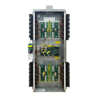
The LMCP-48 has four LMRD boards, with 2 boards placed above and 2 boards placed below the LMPI.
The LMDR boards connect to the LMPI board other with DB9 cables. They must be connected as follows:
• LMCP 8 – Use the top left(#1) DB9 jack.
• LMCP 24 – Use the top left (#1) DB9 jack for the left LMRD board and the top right (#2) jack for the right LMRD board.
• LMCP 48 – Use the top left (#1) DB9 jack for the top left LMRD board, the top right (#2) jack for the top right LMRD board, the
bottom left (#3) jack for the bottom left LMRD board, and the bottom right (#4) jack for the bottom right LMRD board.
Power to the relays comes from the transformers through the LMPI and into the LMRD boards.
Figure 2: LMRD Circuit Board
Override Buttons and Status LEDs 1–6
Relay Status LEDs – The LED will be ON when the relay
turns on, and OFF when the relay turns off. It will blink during
the transition between Normal Hours and After Hours, for the
amount of time specied with the Blink parameter. (If blink time
is set to 0, it will not blink.)
In Smartwire mode, the LED will BLINK on and off when relay
is included in Group, and OFF when relay is excluded from
Group.
In PnL mode, the LED will be ON when relay is selected for
binding with buttons, and OFF when not selected.
Relay Override Buttons –Toggle relay ON or OFF depending
on the state of LED.
In Smartwire mode, selects or deselects relay to be included
into a Group.
In PnL mode, selects relay to be bound to a DLM device.
DB9 Jack – For connection to LMPI
card
Power Indication LED
Remote Override Terminal
P: Pilot signal
C: Pilot common
S: Override signal
C: Override common
Relay Connection Header
12/8 Jumper – For conguring whether the
card drives 8 or 12 relays (jumpered by default
in LMCP8 panels)
Service LED – Blinks once per second if
there is proper communication between
LMRD and LMPI boards. If you press and
hold the button next to the LED, the LED will
remain on instead of blinking.
Override Buttons and Status LEDs 7-12
 Loading...