6
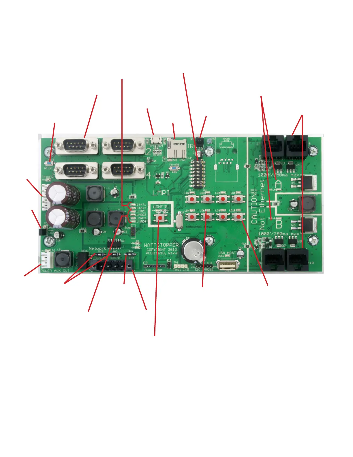
IR Interface – used for
communication with
LMCT-100
RJ-45 jacks for
Connection to DLM
Devices
DB9 Connections to
LMRD Cards
DIP Switches (see details below)
Micro USB Port –
used for updating
rmware
Reset Button – resets
micro-controller chip and is
similar to cycling power on
and off
Microcontoller activity indication LEDs (2 blue). The
LEDs toggle every half second while the microcontroller
is operating. They will both be on solid when AC power is
lost and all power down data has been saved. They will
stop blinking when Factory Defaults Request is happening,
or when rst powered from the factory, until all the data is
initialized.
Room Bus Network Communication Activity
LEDs – Light when communication is active on
room bus A or B.
Transformer
Power
Connector
SW2 – 511 ohm
Bias Up
SW3 – 511 ohm
Pull down
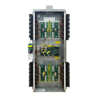
Figure 3: LMPI Circuit Board rev 6
Aux Power
Jumper
Selection
LMRD Communication
Activity LEDs – Light when
communication occurs
between one of the four
LMRD cards.
MS/TP Connector –
For connection to other
panels
Group LEDs – Indicates the
status for Group 1 to 8 for
loads in this panel only, where
any member load ON indicates
ON, and all member loads
OFF indicates OFF. Blinks
during Smartwire mode.
Group Buttons – Toggles Group 1 to 8
when pressed and released. Also used to
enter and exit Smartwire mode.
Panel Cong Button and LED
SW4 – 120 ohm
Termination
Resistor
Dip Switches
The default for all dip switches is OFF.
1-4: Not currently used
5: OFF is used with HDR relays and provides a 20ms pulse. ON is used with RR-7 and RR-9 relays, and provides a 50ms pulse.
6: OFF routes unicast DLM Network messages internally. ON routes unicast DLM Network messages out the RJ-45 jacks. Set this to
ON only if using an external diagnostic tool to view those messages. This will slow down DLM Network communications.
7: OFF turns the relay status LEDs on and off during PnL (but not the relays). ON turns both the relays and status LEDs on and off
during PnL.
8: OFF=Relay status LEDs follow Pilot. ON=Relay status LEDs follow logic (for use with RR-7 relays, which have no pilot wires).
The photo below shows the current version of the LMPI board. The
previous version of the board is shown on the following page.
SD Card Slot –
For future use
Aux Power
Connector
 Loading...