5
JIG ASSEMBLY, MOUNTING, AND USING THE CLAMPS
Chapter 1D4R Pro User Guide
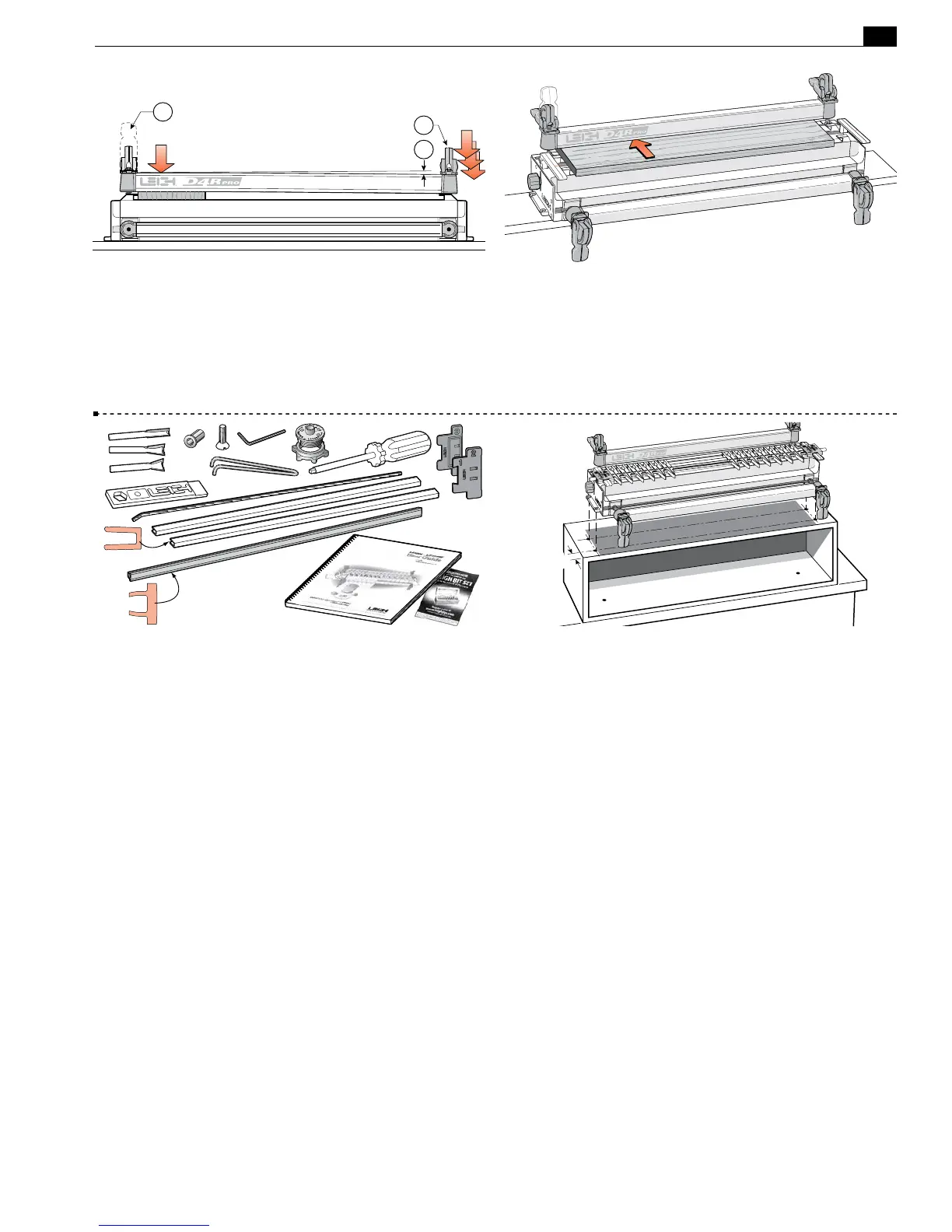
1-19 For all but the wider workpieces, you need only operate
the clamp on the workpiece end
➀
of the jig to release the board.
For narrower boards, the clamp at the free end
➁
should be just
tight enough to bow the clamp bar about
1
⁄8"[3mm]
➂
greatly
exaggerated in this view.
1
2
3
1-20 Make up a spacer board. This board will be used to support
the finger assembly in all front-clamping vertical board modes.
The spac er board should be flat, straight and of even thickness.
We suggest
3
⁄4 "x6"[20x150mm] by approximately 23" [580mm]
long. Note: the thickness of the spacer board has no relationship
to the thickness of the vertical board being routed.
1-21 After you have assembled and mounted the jig, you will
have some items left over:
1 straight router bit Leigh No.140-8
1 dovetail router bit Leigh No.80-8
1 dovetail router bit Leigh No.120-8
1 collet reducer
1 Leigh wrench/gauge
(gauge: Ch.9)
1 accessory attachment screw (Ch.9)
1 hex key, allen wrench
1 Leigh e7 eBush (elliptical guide bushing)
1 pin wrench (eBush adjustment wrench)
1 Leigh guide finger adjustment screwdriver
2 spacers, one for single pass half-blind dovetails
(Ch.11), and
one for box joints
(Ch.15)
2 lengths of bridge piece extrusion (Ch.10)
1 sliding dovetail fence (cross cut fence) (Ch.16)
1 nylon stop rod (Ch.11)
1 fully illustrated user guide (this user guide)
Please keep all these items ready for use.
1 warranty card. Please register your warranty. You will auto-
matically be entered in Leigh’s Warranty Registration Contest.
1-22 To gain height for a more comfortable working position
or for routing longer boards, mount the jig to a box that can be
bolted securely to a bench.
See also fig. 17-15.
■