55
BOX JOINTS
Chapter 15D4R Pro User Guide
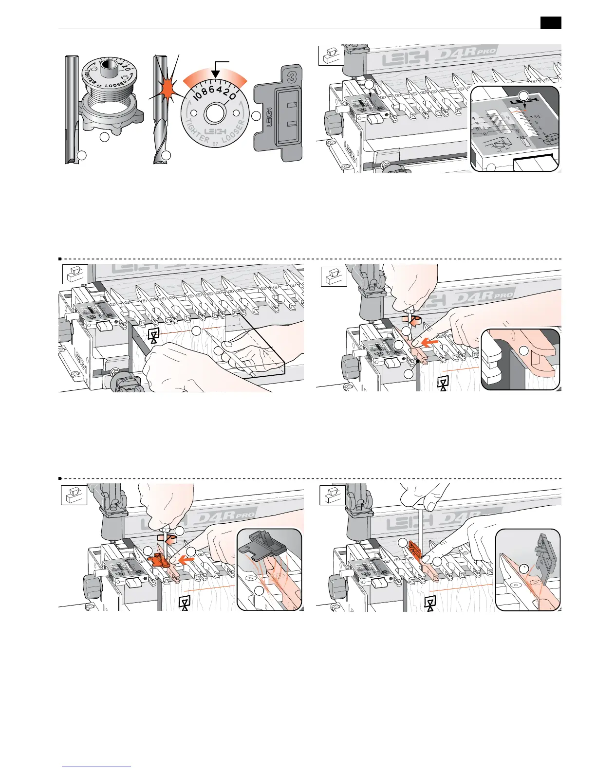
15-1 Bit and Guidebush selection Only the e7-Bush and the
5
⁄16" bit
➀
that came with the D4R Pro are required for box joints.
Spiral upcut router bits
➁
will cut cleaner than straight flute. Where
metric size bits are available an 8mm straight or spiral bit may be
substituted for the
5
⁄16". Always start test routing with the e7-Bush
set on “5”. Note: the box joint Spacer
➂
has a square notch.
5
1
3
21
15-2
3
⁄8"[9,5mm] Box Joints
Place the finger assembly on the support brackets in the HB TAILS
mode, set the scales on the small triangular arrow
➀
and lower
the assembly onto the spacer board. All box joints are routed in
this position. Note: maximum board thickness is 1"[25mm].
1
1
15-3 Clamp a test board in the front left clamp, against the side
stop with the top edge flush under the guide fingers. The board
may be clamped face side in or out
j
. Mark and adjust the depth
of cut to suit the thickness of the mating boards
➀
.
1
15-4 Raise the finger assembly about
1
⁄8"[3mm] to allow ease
of guide finger adjustment
➀
. Position the second guide finger
1
⁄32"[1,0mm] in from the board edge
➁
and tighten the finger.
The first finger stays against the scale block as a router support
➂
.
Note: Square ended boards are essential to achieve flush joint align-
ment.
1
3
2
2
15-5 Place the Spacer on the finger bar to the right of the second
finger, numeral 1 on top overlapping the locked finger
➀
. Move
the next finger in to touch the Spacer
➁
. Hold the guide finger
firmly against the Spacer and tighten the second finger screw
➂
.
As you remove the Spacer you should feel some friction; this
indicates that the guide finger is correctly spaced
➃
.
4
3
1
2
15-6 Now place the spacer vertically on the right hand side of
the third finger; the prongs to the left
➀
. Hold the guide finger
firmly against the Spacer and tighten the second finger screw
➁
.
As you remove the Spacer you should feel some friction
➂
; this
indicates that the guide finger is correctly spaced.
1
3
2
 Loading...

