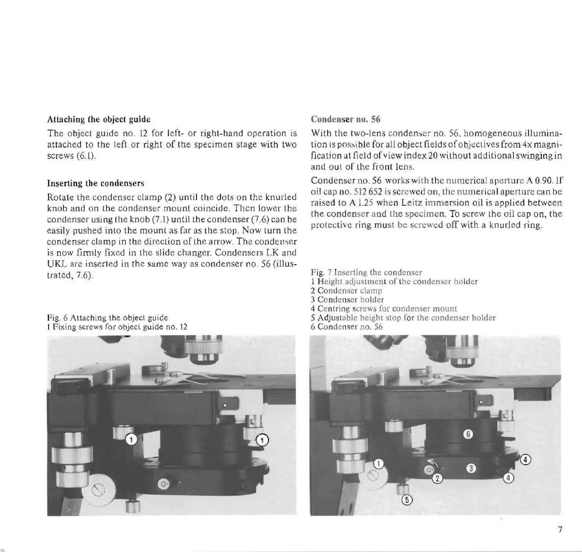
Allaehing Ihe objeel guide
Th
e o
bj
ecl guide no.
12
for left- or right-hand
ope
ration is
allached to the left
or
right
of
the
specimen stage with
tw
o
screws (6.l).
Inserting the condensers
Rotate the
condenser
clamp (2) until the dots on the knurled
knob and on
th
e
conde
nser mount coincide.
Th
en lower lhe
condenser USing the knob (7.1) until the condenser (7.6)can be
eas
ily pushed into the mount
as
far
as
the stop.
Now
turn
th
e
co
nd
en
se
r
cl
amp in the direction orthe a
rr
ow.
Th
e
co
ndenser
is now firmly
fi
xed in the slide
chang
er. Con
de
nse
rs
LK
and
UKL
are inserted in
Ih
e s
ame
way as
condenser
no.
56
(ill us-
Ira ted, 7.6).
Fig. 6 Attaching
th
e object gu ide
1
Fi
xing screws for o
bj
ecl guide no.
12
-
Condenser no. 56
With
th
e
two·lens
co
nden~e
r
n
O.
56.
homogeneo
us illumina-
ti
on is pns>ible for a
ll
object
field s
oro
bj
cc
t;ves from 4x magni-
ficati on
at
fi
e
ld
of
vi
ew index
20
with
o
ut
additional swinging
in
and out
of
the front lens.
Cond
enser no.
56
works with the numerical aperture A 0.90. If
oil cap n
o.
512652
is
screwed
on
, the
num
erical aper
tu
re
can
be
ra
ised to A
1.2
5 when L
ei
tz i
mme
rsion oil is applied betw
een
th
e conden
se
r and the specimen. To screw
th
e oil cap on, the
protecti
ve
ring mu
st
be
sc
rewed
ofT
wi
th
a knurled ring.
F
ig.
7 Inserting the c
on
denser
1 Height adjustme
nt
of
the condenser holder
2 Condenser clamp
3 Condenser holder
4 Cen
tr
in
g screws for c
ondenser
mount
5 Adjustable height stop for the condenser holder
6 Condenser
no
.
S6
.,.-
7