2%
2
1
B
L
2%
2%
2
1
C
L
2%
2%
A
L
2
1
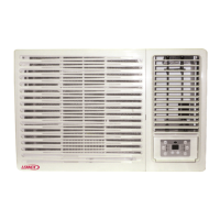
2.7- REFRIGERANT CONNECTIONS
To locate the outdoor and the indoor units, refer to the following information:
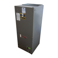
POSITION C : Install a siphon at the base of the vertical of the gas line; no
more siphons are necessary. Maximum vertical length 16m.
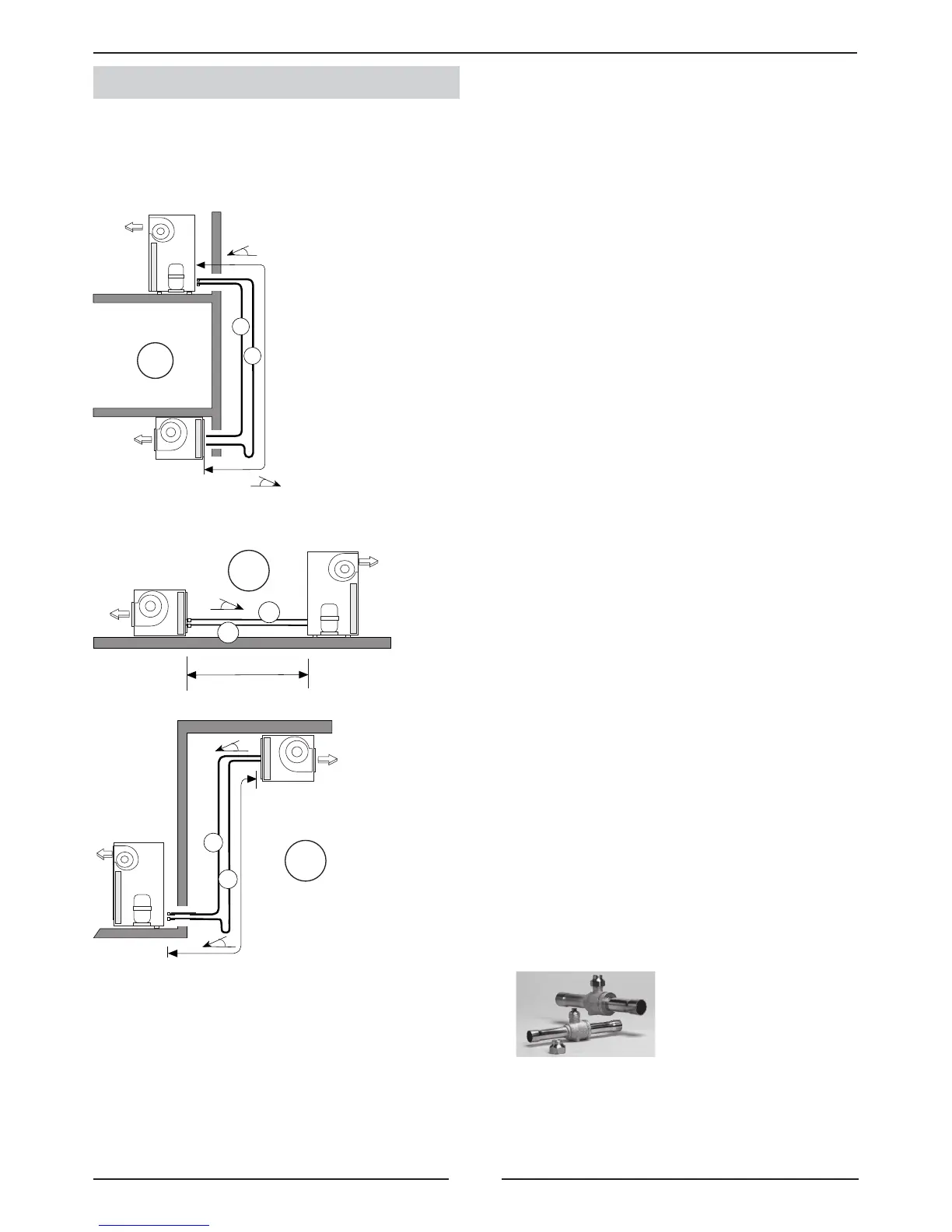
NOTE: The refrigerant connections are brazing
connections. Service valves can be supplied as
option if required.
- THE GAS LINE MUST BE ALWAYS INSULATED.
- THE HORIZONTAL LINES MUST BE TIPPED AT LEAST 2% TOWARD THE OUTDOOR UNIT.
- THE MAXIMUM SPEED INSIDE LINES SHOULD NOT BE MORE THAN 15 m/seg.
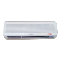
OUTDOOR UNIT
INDOOR UNIT
A,B,C : Unit positions
L : Total length
1 = Gas line
2 = Liquid line
OUTDOOR UNIT
INDOOR UNIT
OUTDOOR UNIT
INDOOR UNIT
POSITION A : A syphon suction must be installed at the base of the vertical of the
gas line, and syphons must be installed every 8 meters upward. The minimum speed
suction must not be below 6m/s. Maximum vertical length 16m.
POSITION B : Tip the lines toward the outdoor unit. Make special attention
to line length longer than 10m and avoid collapse on pipe lines installation.
2.- INSTALLATION