18
INDOOR UNIT
OUTDOOR UNIT
AIR-FLOW
Vapor
Line
LIQUID
LINE
LIQUID LINE
DOOR UNIT
LIQUID LINE TO
INDOOR TXV
TXV
VAPOR
LINE
LIQUID
LINE
MUST BE INSULATED
SULATED
HUMIDITROL
CHARGE
COMPENSATOR
7/8 X 7/8 X
3/8 TEE
UPFLOW POSITION
ELECTRICAL INLET
TO CHARGE
COMPENSATOR
SIDE CONNECTION
(SOME
APPLICATIONS)
CHECK/FLOW
RESTRICTOR TO
VAPOR LINE TEE
LIQUID LINE TO
INDOOR TXV
LIQUID LINE FROM
OUTDOOR UNIT
AIR
FLOW
VAPOR LINE FROM
INDOOR COIL
EDA UNIT
1/4” TUBING
CONNECTION -
MUST BE ON
BOTTOM OF
COMPENSATOR
IMPORTANT!
RESTRICTOR MUST BE INSERTED WITH O-RING
END OF RESTRICTOR TOWARD EDA UNIT FITTING.
TORQUE CHATLEFF CONNECTION TO 20 FT. LBS.
CHECK/FLOW
RESTRICTOR
AND O-RING
FITTING IN EDA UNIT
TEFLON SEAL
USE REDUCER(S)
FROM CHARGE
COMPENSATOR KIT
(WHEN REQUIRED)
12 ft. max.
LENGTH BETWEEN CHARGE
COMPENSATOR AND EDA USING
1/4” LINE PROVIDED IN CHARGE
COMPENSATOR KIT
12 ft. max.
DROP TO CHARGE
COMPENSATOR
CHARGE
COMPENSATOR
7/8 X 7/8 X
3/8 TEE
LIQUID LINE FROM
OUTDOOR UNIT
VAPOR LINE
FROM
OUTDOOR
UNIT
1/4” TUBING
CONNECTION - MUST
BE AT LOWEST POINT
OF THE COMPENSATOR
ELECTRICAL
INLET
TO CHARGE
COMPENSATOR SIDE
CONNECTION
CHECK/FLOW
RESTRICTOR TO
VAPOR LINE TEE
LIQUID LINE TO
INDOOR TXV
VAPOR
LINE
FROM
INDOOR
COIL
Charge
Compensator
Details
USE REDUCER(S) FROM
CHARGE COMPENSATOR
KIT (WHEN REQUIRED)
12 FT MAX. LENGTH TO CHECK/FLOW
RESTRICTOR ON EDA
USE REDUCER(S)
FROM CHARGE
COMPENSATOR KIT
(WHEN REQUIRED)
Check/Flow‐
Restrictor
Details
1/4” PORT MUST
BE BRAZED
CLOSED
NO CHARGE
COMPENSATOR
OR 1/4” LINE
VAPOR LINE FROM
OUTDOOR UNIT
System without
compensator
NOTE 1 - (Any upflow or horizontal application) The physical distance between the evaporator coil
and the EDA unit can be extended so long as all of the evaporator coil air flow also flows through
the EDA coil and the 12 foot line length limitations are met.
See NOTE 1 near
bottom of page.
12 FT MAX. LENGTH
TO CHECK/FLOW
RESTRICTOR ON EDA
TYPICAL HORIZONTAL POSITION INSTALLATION
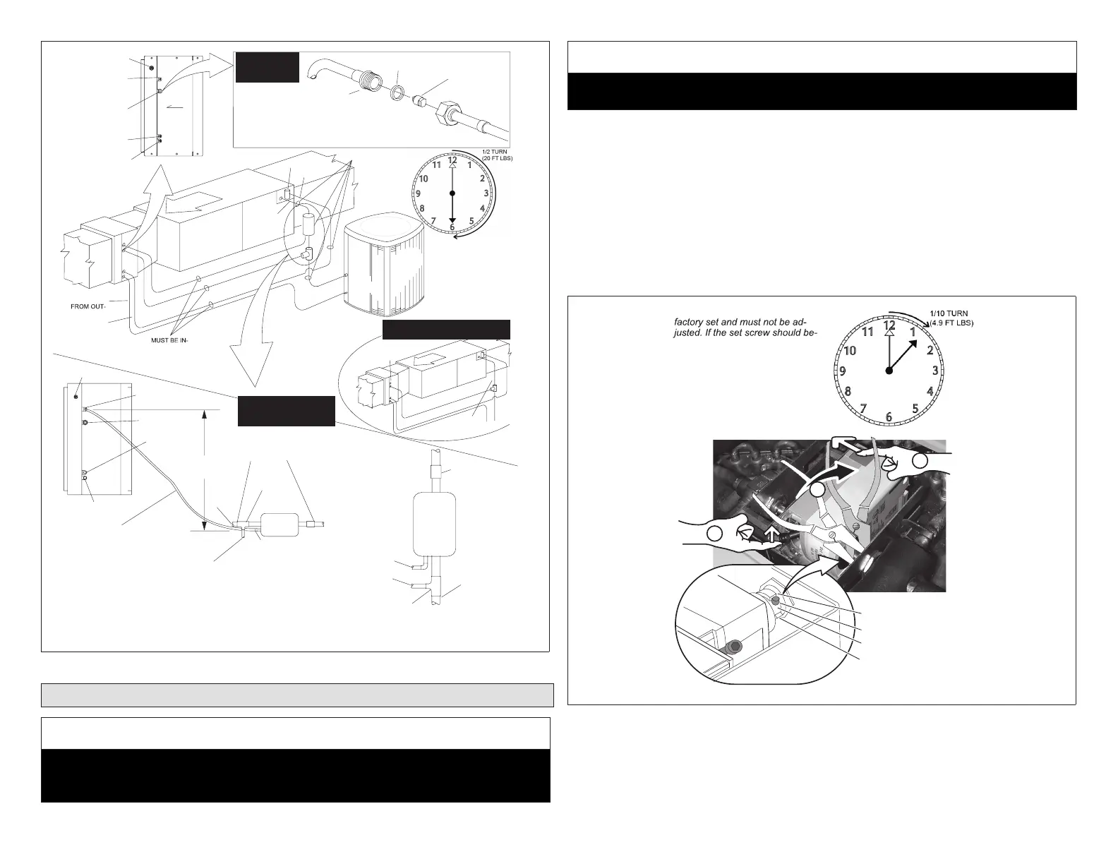
Figure 17. Typical Installation (Horizontal Air Handler Shown)
2.4. Leak Testing, Evacuating, Charging
IMPORTANT
The 3-way diverting valve actuator shaft pinch bolt (see “Figure 19. Setting
3-WayDivertingValve toEvacuatePosition”onpage19) isfactorysetandis
nottobeadjusted.
IMPORTANT
Priortostartingtheoutdoorunitforcharging,besurethe3-wayvalveisener-
gizedandinthe“cooling”(forward)position(seeFigure18).
2.4.1. 3-Way Diverting Valve Operation
NOTE: During system operation, the 3-way valve requires 24-volt power to drive
between cooling and dehumidication.
The3-way diverting valveis actuallytwovalves connectedbya commonshaft,
designedtoopenonevalvewhileclosingtheother,andvice-versa.Forevacuating
(withpoweroff),thedivertingvalvecanberepositionedusingitsactuatorlever,a
longpinchboltthathasbeenfactory-settoaprecisepointonthecommonshaft.Do
notloosen(unscrew)thepinchbolt.Shouldthepinchboltbecomeloose,carefully
followthenoteinthefollowingguretopositionandtightenit.
NOTE - Actuator shaft pinchbolt is
come loose, use pliers to grip the
shaft where shown (1) and rotate
the shaft (in direction of the black
arrow) until the pin stops (inset
shows pin and stops). Press the
red button (2) in the direction of the
white arrow and move the lever (3)
to the forward position and tighten
pinchbolt to 60 in‐lbs torque.
STOP
PIN
SHAFT
STOP
2
3
1
Figure 18. Re-Aligning Pinch Bolt