21
3.2. iComfort E30 and S30 Thermostats
The thermostat must be configured to properly operate
the Humiditrol as follows:
1.Touch
ner.
2.Touch the settings icon
3.From the menu along the left side of the screen
touch the advanced settings option.
4.Touch view dealer control center.
5.Warning message will appear, read and touch
proceed.
6.From the dealer control center screen, touch
equipment.
7.From the menu along the left side of the screen
touch add/remove equipment.
8.Touch Humiditrol under the Dehumidifier option.
A check mark will indicated it has been selected.
9.Go to Equipment > Smart Hub and go down the list
until you reach Humiditrol Comfort Adjust.
2:31 am
tue | Mar 31, 2015
Options are Maximum Overcooling, Midpoint
Overcooling and Minimum Overcooling. Default is
Maximum Overcooling.
Maximum Overcooling: Indoor temperature
> (greater than) 2°F above heating setpoint.
Midpoint Overcooling: Indoor temperature
point / 2.
Minimum Overcooling: Indoor temperature
> (greater than) 2°F below cooling setpoint.
Maximum allowed set point for humidification.
Range is 15 to 45%. Default is 45%. Adjustments
Figure 22. E30 and S30 Thermostats—Add and Adjust Humiditrol
3.3. iComfort M30 Thermostat
The thermostat must be configured to properly operate
the Humiditrol as follows:
1.Touch
ner.
2.Touch the settings icon
3.From the menu touch the advanced settings
tion.
4.Touch humidity option. Under
trol, select dehumidify
tion. By default it is disabled.
5.There are four setting options which are Normal,
Max, Humiditrol* and Aux Dehumidifier (requires
hardware accessory installed). Slide bar adjust
with a range of 40% to 60% RH.
6.For further details concerning the normal or max
setting
fer to the iComfort M30 Installation and Setup
Guide.
2:31 am
tue | Mar 31, 2015
Figure 23. M30 Thermostat—Add and Adjust Humiditrol
4. modes of operatIon
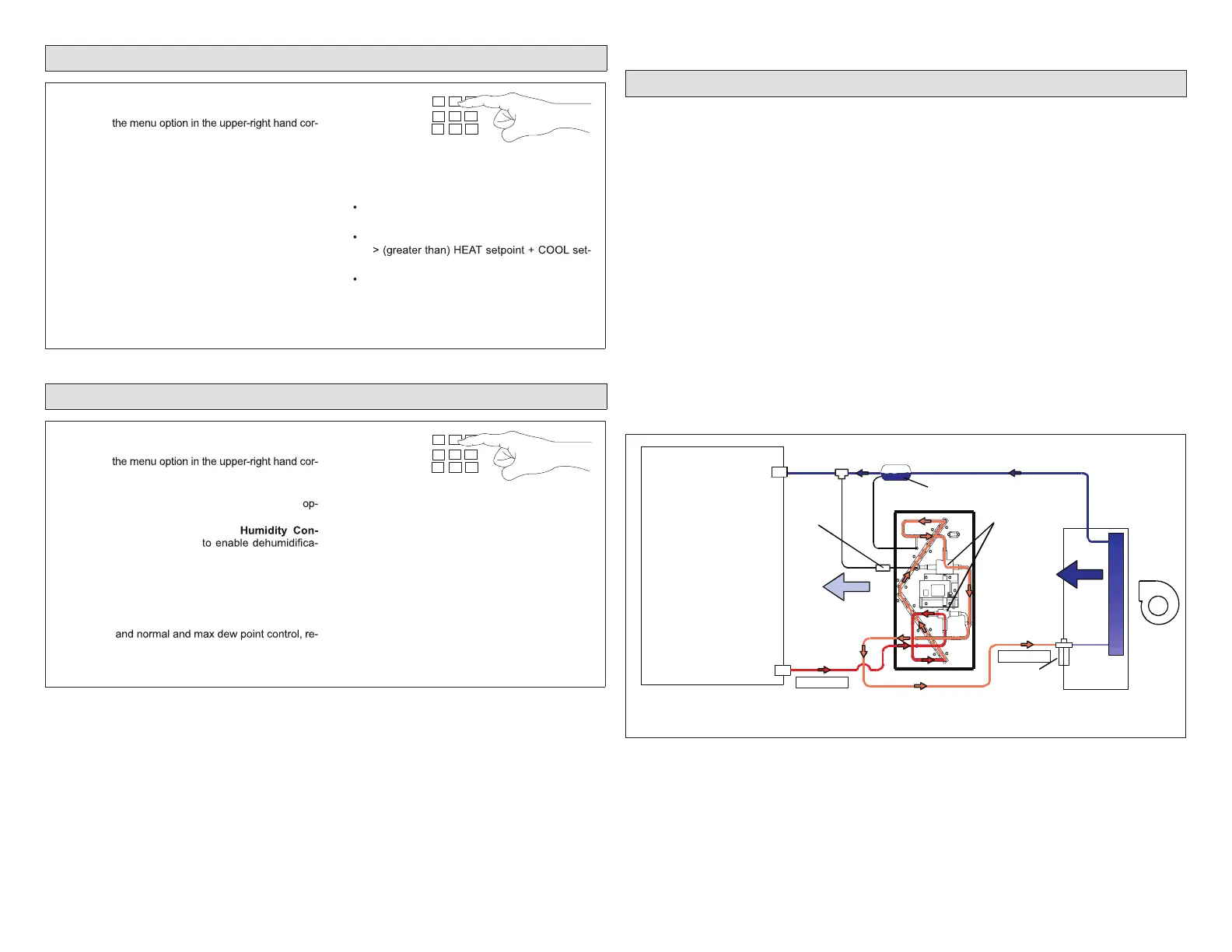
4.1. Dehumidication Mode (Cooling ON)
Iftheroomthermostat’scoolingdemandhasbeensatisedbutthedehumidication
settinghasnotbeensatised,theunitcontinuestorunindehumidicationmode.
TheroomthermostatsendsasignaltotheHumiditrolunit’s3-waydivertingvalve
assemblytobeginoperatinginthedehumidicationmode.
Figure24showsrefrigerantowingfromtheoutdoorunit,enteringtheHumiditrol,
passingthroughtherst3-waydivertingvalve,thenenteringtheHumiditrolcoil.
Theheatfromthewarmrefrigerantistransferredintotheindoorairstream.The
refrigerant exits the coil through the second 3-way diverting valve and into the
indoorcoilexpansionvalve.
Duringdehumidication,theindoorairblower(andoutdoorfan,ifanoutdoorrelay
is used) operates at a lower air volume. The cool, dehumidied air leaving the
indoorcoil iswarmed asit passesover theHumiditrol coil.Airtemperature rise
acrossthe Humiditrol coil can befrom 10°to 25°F,depending onthe operating
ambientandair-conditionedspaceconditions.
The warm vapor-liquid-refrigerant mixture entering the Humiditrol unit from the
outdoorunitwillbesub-cooledintheHumiditrolunitandentertheexpansionvalve
atalowerthannormaltemperature.Liquidtemperaturescanbeinthe65°to70°F
range,witha10°to40°FtemperaturechangeacrosstheHumiditrol.
3-WAY
DIVERTING
VALVE
CHECK/FLOW
RESTRICTOR
(flow restricted)
VAPOR
LINE
VALVE
7/8 x 7/8 x
3/8 TEE
(furnished)
CHARGE COMPENSATOR
(Holding refrigerant) See note 3.
LIQUID
LINE
VALVE
OUTDOOR UNIT
INDOOR
BLOWER
CHECK/
EXPANSION
VALVE
INDOOR UNIT
See note 2
AIR FLOW
see note 1
AIR FLOW
see note 1
NOTE 1. With EDA Coil Active, expect a 10 to 25ºF air temperature rise across EDA coils.
NOTE 2. With EDA Coil Active, expect a 10 to 40ºF liquid line temperature change across EDA coils.
NOTE 3. Charge compensator and 1/4” line not required on all systems. See Product Specifications.
INDOOR COIL
See note 2
Figure 24. Dehumidication Cycle with Humiditrol Coil Active (Model
EDA-036C Shown)

 Loading...